Table of Contents

IH: Oiling & Lubrication
Engine Oil System
The Sportster Oiling Cycle is defined in the FSMs.
However, that description is vague in some of the intricate transitions of the oil path in the engine.
This page is an attempt to clarify some of the gray areas from the FSM's descriptions with further description and pictures. 1)
Links to other Oiling pages in the Sportsterpedia:
Oil Path Drawings: Click on a drawing below to enlarge. 2)
Engine Oil Cycle (1976 and Earlier)
Oil is gravity fed from the oil tank to the oil pump. 3) A check valve in the oil pump prevents the oil from draining into the engine by gravity. Then, the oil pump supplies pressurized oil into a hole in the cam cover. That pressurized oil is forced up the lines (between the cylinders) to the rocker box by the oil pump. That is the vertical end of responsibility (pressure wise) for the oil pump. In the rocker boxes, oil gathers and splashes over rocker arm bearings and rods, valve stems, valve springs and pushrod sockets. Before the oil reaches the rocker lines, it splits off to a hole through the pinion shaft (to get to the lower rod bearings). This is the horizontal end of responsibility (pressure wise) for the oil pump. From here on, oil travels through the engine by way of gravity, vacuum and splash motion.
Oil drains from the heads through passages in each cylinder. Then it flows into two holes in the base of each cylinder while lubricating the cylinder walls, pistons, rings and main bearings.4) Oil flows from the rocker boxes into the gearcase compartment through the pushrod tubes. Parts lubricated by this include the pushrods, tappets, tappet guides and tappet rollers and cam gears.
Oil accumulated in the crankcase base is scavenged by the flywheels to the breather oil trap. The rotary breather valve is timed to open on the downward stroke of the pistons. This allows crankcase exhaust air pressure to expel scavenge oil from the crankcase breather oil trap into the gearcase. The breather valve closes on upward stroke of the pistons, creating vacuum in the crankcase.
This splash oil blown from the crankcase to the gearcase lubricates the generator drive gear, cam gears and cam bearings. Crankcase exhaust air escapes from the timing gearcase through the outside breather tube.5) Any oil still carried by exhaust air is separated form the air by an oil slinger on the generator drive gear.6)
Gearcase oil flows through the fine mesh oil strainer preventing foreign particles from entering the scavenge section of the oil pump.7) Engine oil returns to the oil tank by the scavenge side of the oil pump and also supplies oil to the rear chain oiler.
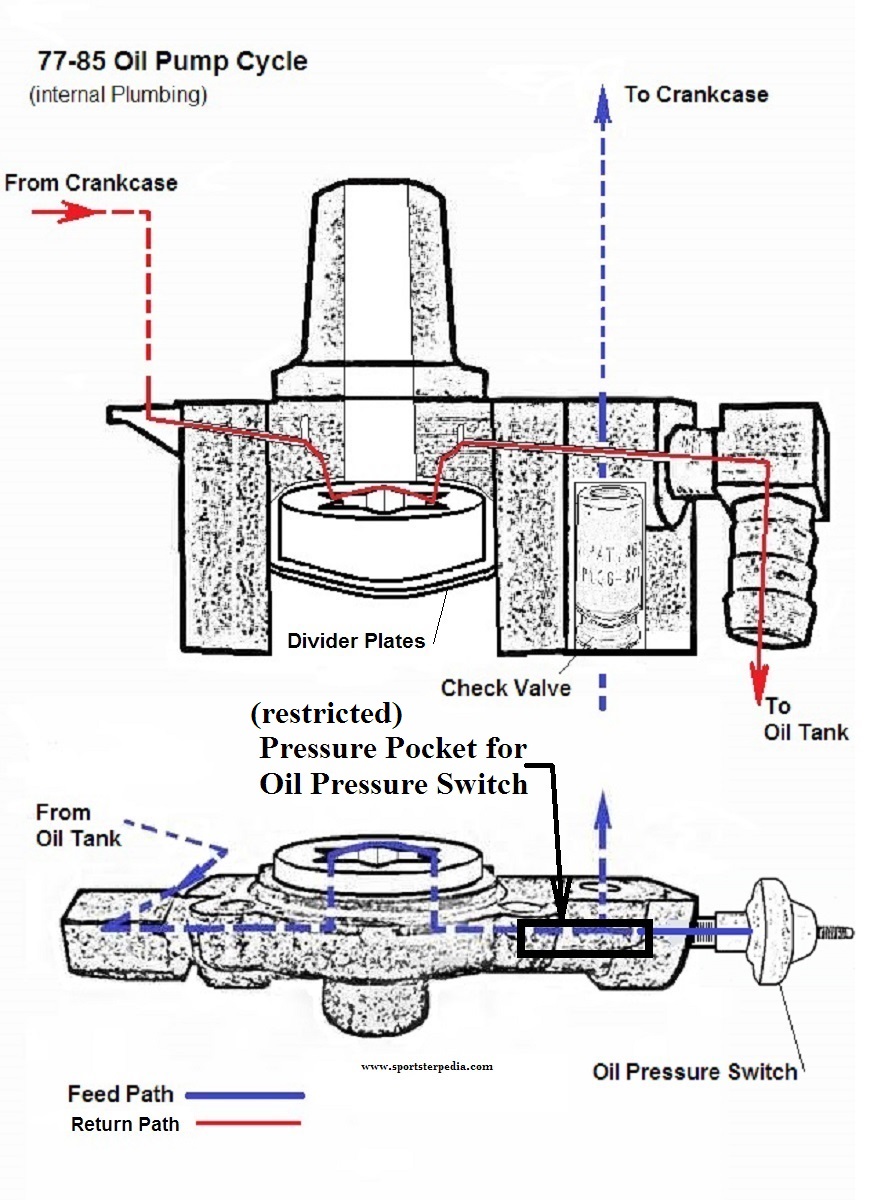
Engine Oil Cycle (1977 to 1985)
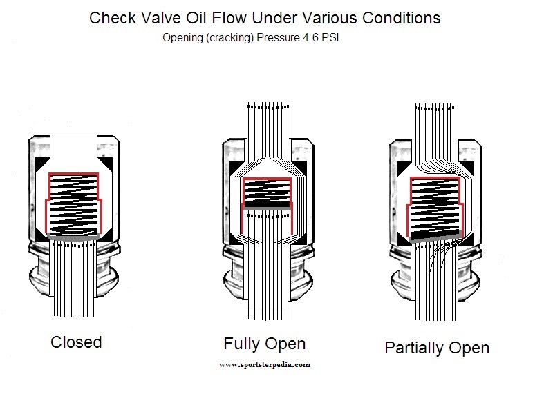
Oil is gravity fed to the gerotor type oil pump. Oil enters the feed section and fills a cavity under the feed pump. Oil is transferred from the inlet cavity to a one way check valve located in the outlet line. 8) The check valve prevents gravity oil drainage from the oil tank to the engine and acts as a restriction to activate the pressure switch. The check valve is set to open between 4 psi and 6 psi of oil pressure. 9) As the oil pump pressurizes, it causes the oil pressure indicator light, sending unit to activate and the check valve opens. With the check valve open, oil flows into the right case half through a hole located in the oil pump gasket surface and into the gearcase cover passage through a hole in the gearcase cover gasket. 10) Oil is routed to the crankshaft and to the head areas. Oil enters a hole in the pinion gear shaft and travels to the right flywheel then through the flywheel to the crank pin. Oil is forced out of the crank pin through 3 holes located to properly lubricate the rod bearing assembly. 11) Oil that bypasses the pinion gear shaft travels upward through the gearcase cover to the right crankcase and through a channel in the crankcase to the overhead lines to both front and rear intake rocker arm shafts, lubricating the rocker arm shafts, bushings, intake valves and pushrods. 12)
Oil continues around a groove machined in the outside diameter of the large end of the rocker arm shaft and through the rocker arm arm cover to the exhaust rocker arm shaft lubricating the rocker arm bushings, valves and pushrods in the same manner as is described for the intake shafts. 13) Oil collected in the pushrod area of the heads flows down the pushrod covers to lubricate the lifters. The lifter's rollers are lubricated by oil draining into the gearcase through the 2 drain holes in the lifter bodies. 14) Oil collected in the valve spring pockets drains to the flywheel compartment through horizontal holes in the cylinders. Oil returning from the heads, rod assembly and gearcase collects in the sump area below the flywheels. 15)
Oil collected in the sump area returns to the scavenger section of the oil pump through a passage located in the rear section of the pump. Oil flow to the pump is accomplished by the scavenger effect of the oil pump and the pressure created from the downward stroke of the pistons. 16) Return oil fills a cavity above the scavenger section of the pump which transfers return oil to the outlet side of the pump and sends the oil back to the oil tank.
All engine breathing is accomplished through the gearcase into the breather system. Any oil still carried by the exhaust air is centrifugally separated from the air by an oil slinger on the end of the generator drive gear shaft. 17) Crankcase exhaust air is routed through a one way check valve to the air cleaner. 18)
Oil Feed System
Sub Documents
The engine has a force-fed (pressure type) oiling system incorporating oil feed and return pumps in one pump body with a check valve on the feed side.
Role of the Oil Tank
Click Here to reference the Ironhead Oil Tank section in the Sportsterpedia.
Click here to reference the Oil Tank Pressure page in the Sportsterpedia.
The oil tank is both an oil reservoir and air/oil separator. Return oil comes into the tank carrying both air and oil.
The oil drops to the bottom while air rises up and out the vent back to the cam chest.
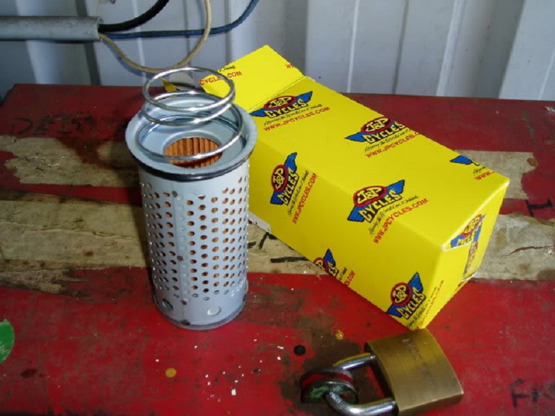
From 1957-1978, the oil tank is also a housing for the oil filter on XL / XLH models. XLCH models didn't have a factory installed oil filter.
Oil is gravity fed from the oil tank to the oil pump. What that means is since the oil tank is higher than the pump, gravity pushes oil down to the pump inlet but not into a running motor. It's basically a byproduct of hanging the tank above the pump. Gravity does assist pump suction however. A pressure of less than 1/4 PSI was calculated in the link below as an example on a 1998 model Sportster setup. That 1/4 PSI is just for example only as elevation and oil density will slightly change that number. The point of stating that is there is very little (but needed) gravity oil pressure on the oil at the pump inlet.
Click Here to read more on calculating Oil Tank Head Pressure at the pump in the REF section of the Sportsterpedia.
Pressure from gravity constantly pushes oil to the pump's inlet which helps the pump pick up oil through suction from there.
The higher the oil tank sits, the higher the oil level sits which increases the NPSHA which is the (Net Positive Suction Head Available) to the pump.
Click Here to read more on NPSHR vs NPSHA in the REF section of the Sportsterpedia.
The pump requires a positive push of oil to the inlet cavity to function as designed.
Pressure from gravity is also the reason oil from the tank can leak down into the motor when the motor is shut down.
Click Here to read more on Sit Sumping in the REF section.
It's not unusual to get air out the oil return line (to the tank). 19) It's a dry-sump system with an oil pump that's designed to keep the engine sump as dry as it can. When there's no oil to suck up, it pumps air instead into the oil tank. That's the way it's supposed to work.
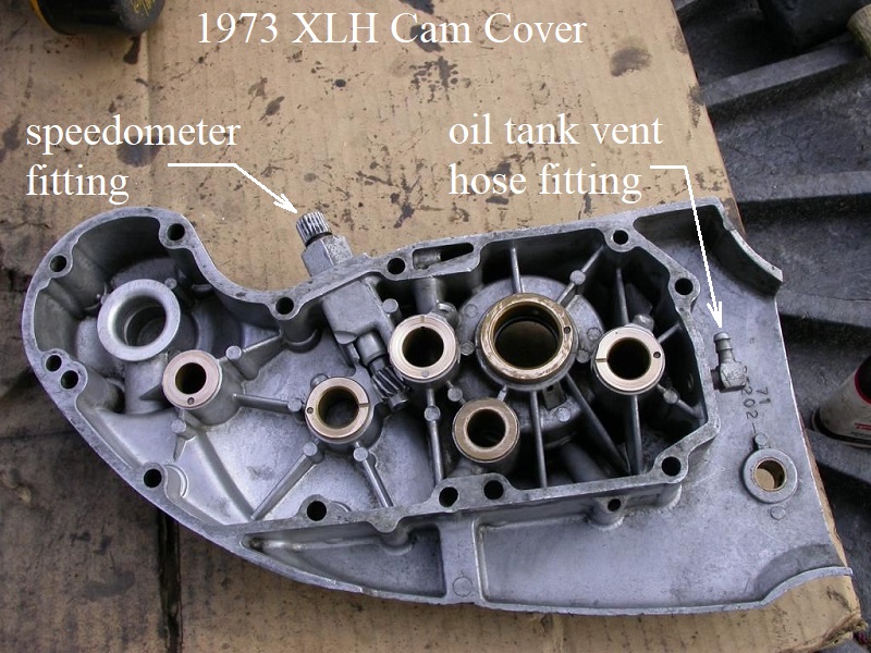
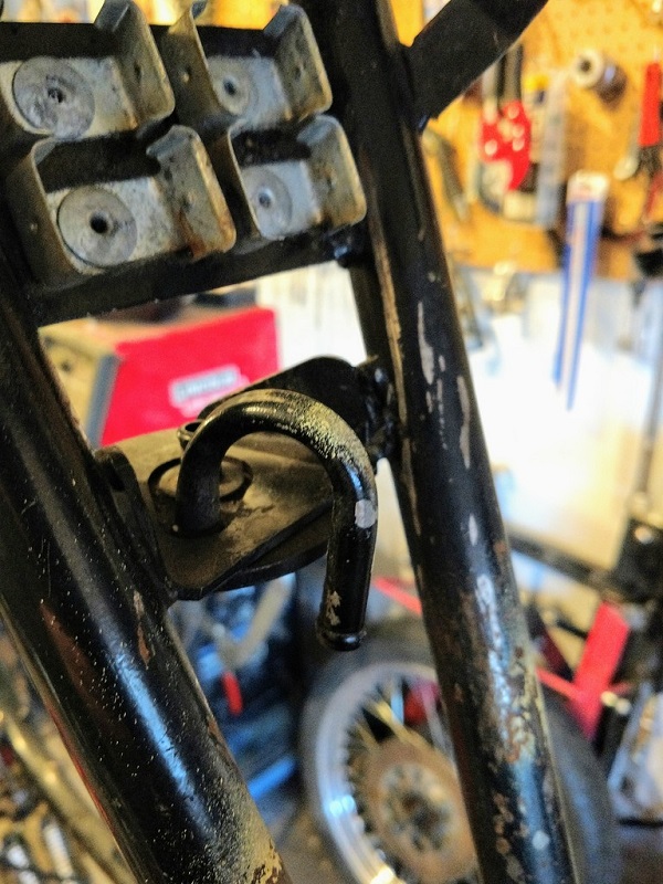
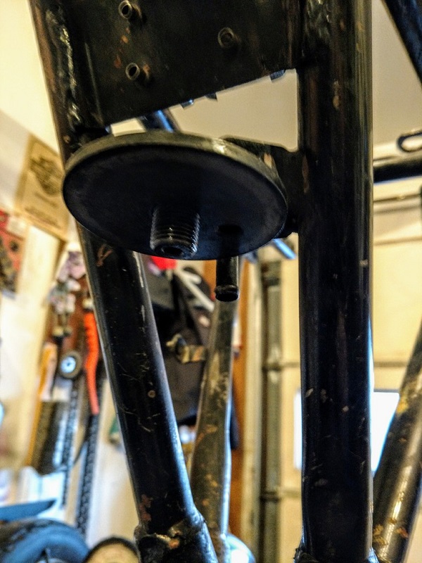
The oil tank vents separated air back to the gearcase. The vent line from the tank mostly vents oil tank air back to the gearcase mixed with an oil mist. If the vent line is kinked or blocked, pressure will back up in the tank and pop the cap and splash oil everywhere. 1957-1966 XLH and 1958-1969 XLCH engines vent the oil tank to the gearcase by a hose attached from the oil tank to a fitting on the top of the engine behind the rear cylinder. There is a passage in the engine case that routes from there into the gearcase. 1967-up XLH and 1970-up XLCH engines vent the oil tank to the gearcase by a hose from the oil tank a 90° fitting on the rear of the gearcase cover.
| Oil tank vent fitting on 1973 XLH 20) |
 |
Role of the Oil Pump - Pressure
Click Here to reference the oil pump section in the Sportsterpedia.
The feed side of the oil pump forces oil to the engine to lubricate the lower connecting rod bearings, rocker arms and bushings, valve stems, valve springs, and pushrods (and cam gears on 1985 models only). The pressure side of the oil pump is non-regulated and delivers its entire volume of oil under pressure to the engine feed system.
Different areas of the motor have different types of pressure applied and from different sources. 21) 22)
The same applies to the oil pump.
Oil pump feed gear / gerotor vacuum sucks oil from the inlet cavity or attached hose respectively into the inlet cavity of the pump. There is a vacuum created on the inlet cavity of the pump generated by the opening of the gears / gerotors when they rotate around to the inlet side of the pump. Vacuum is aided by the positive force of gravity from the higher hung oil tank as mentioned above. 23) Without vacuum, the pump would not be able to function properly and would starve the pump especially at higher RPM. As the volume between the feed gerotor (or gears respectively) increases with engine RPM, the suction on the feed line also increases. 24) Likewise with lower RPM, the suction decreases.
Too low suction and the gear / gerotor cavities will not completely fill with oil especially on higher RPM and system oil volume will suffer. Too much vacuum and oil vapor may be pulled out of the oil stream and cavitate / damage the oil pump. Thankfully, the MoCo has designed the OEM oiling system in the Sportster to keep this from happening.
The oil pump pressurizes the oil delivered to the outlet cavity in the pump. One teeth cavity of oil at a time is rotated from the inlet side to the outlet side in the pump. The closing of the teeth afterward combined with the next teeth full of oil continues squeezing (pressurizing) the outlet cavity. The faster the rotation, the higher the pressure that is created in the outlet of the pump.
The engine is force-fed oil by system pressure. Pressure is always greatest at the oil pump outlet. Restrictions in the oil feed path lower the pressure past them depending on how much of a restriction is created and for how long. The constant squeezing of the gears / gerotors creates measurable pressure discharge but not equal to system pressure.
Engine Oil Pressure, Volume and Testing
Sub Documents
Click Here for the “Sportster Oil Pressure (1957-Present)” page in the REF section of the Sportsterpedia“.
That page consists of where to test, expected oil pressure for the respective year models and a link to the page for installing a pressure gauge.
On Ironheads, 80% of oil pressure is sent to the bottom end and 20% is sent to the top end according to MMI. 25) Ironhead engine oil pressure is measured (by the MoCo) with a pressure gauge at the oil pump. The pressure throughout the feed system will always be highest at the oil pump.
The FSMs say the oil pump is non-regulatory and delivers its entire volume of oil under pressure to the motor. But that is not the entire story.
Cold oil flows slower and at higher pressure than hot oil. During start-up of a cold (ambient temp) engine, oil is thicker, oil pressure will be higher than normal and oil circulation will be somewhat restricted to flow within the oiling path. Oil pressure should be checked when hot (operating temp) to meet the specs in the manuals. As the oil heats up it gets thinner, flows faster and pressure is lowered.
The oil path, as designed, creates variable system pressures. The restrictions in the oil feed path (hose size, routing paths, orifice sizes, etc) manipulate oil flow and oil pressure. Each restriction in the feed path, whether chamber size, bends or orifice size, lowers the flow volume and pressure downstream of the restriction. I.E., A restrictor placed in the end of the pinion shaft will lower the amount of oil that gets passed it to the crankpin/lower end bearings but the smaller amount of oil that does flow past the restrictor flows at a faster rate. And lowering the amount of oil to the pinion shaft also sends more oil up to the rocker boxes. There will be lower pressure at the crankpin / lower end bearings than at the oil pump. There will also be lower pressure at the rocker arms then there will be at the oil pump. The OEM specs were meant to show the amount of pressure that should be present at the pump without further modifications to the feed system. Altering the OEM feed path will change the pressure at the pump to the extent of the modification.
Restrictions in the oil path harness and manipulate the pressure created at the pump. Pressure is always greatest at the oil pump outlet. As the oil passes each restriction (bends, smaller passages, orifices as well as elevation), pressure will be lower from thereon depending on how much of a restriction is created and for how long.
Oil volume to the motor is dependent on RPM. When an engine is operated at higher speeds; the volume of oil circulated through the oiling system increases, resulting in higher oil pressure throughout the feed path. As engine speed is reduced, the volume of oil pumped is also reduced, resulting in lower oil pressure throughout the feed path.
Oil Pressure Light
If the oil pressure light stays on at speeds above idling, always check the oil supply first.
Then if the oil supply is normal, look inside the oil tank to determine if oil is returning to the tank from the return hose with the engine running.
If oil is returning to the tank, there is some circulation and the engine may be run a short distance if necessary.
If no oil is returning, shut the engine off until the trouble is located and fixed.
Conditions causing the oil light to stay on;
Low or diluted oil supply,
Or a plugged lifter screen (86-91) under the plug between the tappets,
A grounded oil signal switch wire,
Faulty oil switch,
Faulty or weak oil pump,
Clogged feed hose (in freezing weather from ice and sludge preventing the circulation of oil).
Year Model Specifics
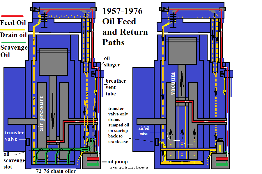
Refer to the drawings at the top of this page from the text below.
1957-1976
Oil pump feed gears send pressurized oil through a check ball mounted in the oil pump. Oil leaves the oil check and enters a hidden passage in the cam chest floor up through the cam cover internal passages to the pinion bushing / shaft. Oil is sent thru the pinion shaft to internal holes in the right flywheel to the crankpin and out to the lower end rod bearings. This is the end of oil pump pressure in the lower end.
Oil is also sent past the pinion bushing thru an internal passage in the cam cover to the upper feed galley in the top of the gearcase. There is a hole in the upper cover that opens to a horizontal drilled hole in the upper right case. Oil leaves the cam cover into the upper case galley and into 2 external oil lines attached on the top of the gearcase. Both oil lines are fed by the same “oil galley” in the case. The oil lines run up and attach to the rocker boxes (front tube to front rocker box, rear tube to rear rocker box). Pressurized oil flows up each external tube into their respective rocker box. The tubes are fed “system” pressure but not as much as what is present at the oil pump. Pressure from the oil pump has been altered (lowered) by the time it gets to the rocker boxes. Oil is routed into each rocker box by “closed channels”, so not the entire rocker box gets pressurized. Oil from each oil line is routed into the box, around the big bushing machined into the rocker arm bolt, thru a drilled channel to the next rocker arm bolt bushing. Oil enters a hole in each rocker arm bolt, thru that bolt and out a hole that sits under the rocker arm, thus pressurizing the rocker arm ID. Oil leaves the rocker arms thru the rocker bolt bushings and small holes underneath the “fingers” that actuate the valves. These small holes act as cooling jets onto the valves. This is the end of oil pump pressure in the top end.
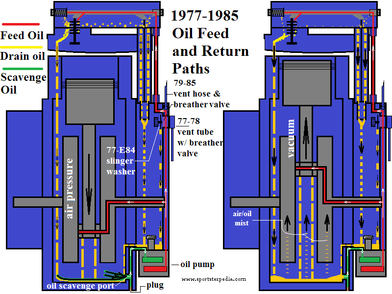
1977-1985
Oil pump feed gerotors send pressurized oil through a check valve mounted in the oil pump. Oil leaves the oil check and enters a hidden passage in the cam chest floor up through the cam cover internal passages to the pinion bushing / shaft. Oil is sent thru the pinion shaft to internal holes in the right flywheel to the crankpin and out to the lower end rod bearings. This is the end of oil pump pressure in the lower end with the exception being 1985 models. Starting with crankcase number 785 303 002, manufactured after October 29, 1984, a spray tube was installed into the upper gearcase above the cams. The tube carries pressurized oil from the upper oil feed galley that exits out tiny holes in the tube to give the cams a constant spray of oil for extra cooling.
Oil is also sent up past the pinion bushing thru an internal passage in the cam cover to the upper feed galley in the top of the gearcase. There is a hole in the upper cover that opens to a horizontal drilled hole in the upper right case. Oil leaves the cam cover into the upper case galley and into 2 external oil lines attached on the top of the gearcase. Both oil lines are fed by the same “oil galley” in the case. The oil lines run up and attach to the rocker boxes (front tube to front rocker box, rear tube to rear rocker box). Pressurized oil flows up each external tube into their respective rocker box. The tubes are fed “system” pressure but not as much as what is present at the oil pump. Pressure from the oil pump has been altered (lowered) by the time it gets to the rocker boxes. Oil is routed into each rocker box by “closed channels”, so not the entire rocker box gets pressurized. Oil from each oil line is routed into the box, around the big bushing machined into the rocker arm bolt, thru a drilled channel to the next rocker arm bolt bushing. Oil enters a hole in each rocker arm bolt, thru that bolt and out a hole that sits under the rocker arm, thus pressurizing the rocker arm ID. Oil leaves the rocker arms thru the rocker bolt bushings and small holes underneath the “fingers” that actuate the valves. These small holes act as cooling jets onto the valves. This is the end of oil pump pressure in the top end.
Oil Drainage
Sub Documents
Drain oil is not a part of the feed pressure system. Drain oil is non-pressurized oil that exits the last orifice in the respective pressure path and eventually finds it way to the crankcase or cam chest floor awaiting to be scavenged by the oil pump. Once pressurized oil exits it's last orifice, pressure dissipates and is generally (at atmosphere) from there on.
Excess oil in the rocker boxes drains to the lower end. Some drain oil from the rocker boxes falls to the crankcase by way of 2 drain holes in each head and cylinder while lubricating the cylinder walls, pistons, rings and main bearings. And some drain oil from the rocker boxes falls down the pushrod tubes, through channels in the lifter blocks to the gearcase compartment, lubricating the pushrods, tappets, tappet guides, tappet rollers and cam gears.
Drain oil is subject to the variable changing crankcase air pressure. Drain oil aides in splash lube since some of that is picked up into air/oil mist and slung onto the moving parts by crankcase pressure pulses and the moving parts themselves.
There will always be an amount of oil left in the cases after shutdown. A large portion of drain oil hits the bottom of the crankcase or cam chest and exits the motor by way of the oil pump and sent back to the oil tank during operation. During shutdown, there will be oil in the feed passages, up top in the boxes, on the flywheels and cams etc. that will fall back down to the gearcase and crankcase floors and will not be scavenged since the motor is not running.
There may also be a certain amount of oil that drains into the motor from the oil tank after shutdown. This has been affectionately hailed as Sit Sumping on the XLForum. Click Here to read more on sit sumping in the Sportsterpedia. There are generally 2 areas of suspect where oil can drain into a non running motor; oil check ball/check valve or the seal in the top plate of the oil pump. (1) The oil check ball/valve in the oil pump can allow oil to seep from the tank, between the gears/gerotors and up into the motor via the oil feed path. (2) Too wide of clearances or worn parts in the oil pump can allow oil to seep up into the gearcase to the crankcase. Keep in mind that oil expands when hot. So checking the oil level as soon as you shut off the motor then checking it an hour later may only show the oil shrinking when cold and may not mean the loss on the dipstick went into the motor. Checking when the oil cools down then checking hours/days/weeks later may give better longstanding results.
Oil Return System (scavenge)
Sub Documents
Role of Crankcase Pressure
See also in the Sportsterpedia:
Positive crankcase pressure (piston downstroke) aides the scavenging ability of the pump. Just like the feed side needs the positive push from gravity oil by way of the higher strung oil tank to operate efficiently, the return side needs a positive push of oil to their return side inlet cavity to operate efficiently and the positive push from each piston downstroke serves that purpose. The positive air pressure increases the NPSHA (Net Positive Suction Head Available) to the pump which allows the pump's suction force (vacuum), created inside the pump by the opening of the gear / gerotor teeth.
Click Here to read more on NPSHR vs NPSHA in the REF section of the Sportsterpedia.
Negative crankcase pressure (or vacuum from piston upstroke) makes the pump's job harder since the pump is fighting the crankcase vacuum. Crankcase vacuum decreases NPSHA to the pump and the pump sucks oil only when oil is present in the inlet of the pump (from the gearcase drain compartment or sump port respectively). The more vacuum in the crankcase/gearcase, the less oil the pump can pick up on average.
1957-1976 engines:
Positive crankcase pressure blows air and oil, from the crankcase, into the oil trough in the rear of the crankcase clear to the cam chest return cavity near the inlet side of the oil pump's return gears. The crankcase, oil tank and gearcase all share the same air space so when one is pressurized, all are pressurized. Downstroke positive pressure in the gearcase serves as NPSHA to the oil pump, allowing the pump to operate efficiently.
1977-Up engines:
Positive crankcase pressure (piston downstroke) blows oil to the exit port in the rear of the crankcase sump where it is sucked uphill to the oil pump by way of pump vacuum. Again, downstroke positive pressure in the gearcase serves as NPSHA to the oil pump, allowing the pump to operate efficiently.
Role of the Oil Pump - Scavenge
Click Here to reference the Ironhead Oil Pump section in the Sportsterpedia.
The scavenge side of the pump returns oil from the bottom of the gearcase and crankcase sump to the oil tank.
Oil pump pressure and crankcase pressure work together to remove oil out of the motor.
Oil pump suction
Just as with the feed side, a vacuum is created on the inlet cavity of the return side generated by the opening of the gears (or gerotors respectively) as they rotate around to the inlet side of the pump. Pump vacuum is aided by the positive force of piston downstroke (57-76 in the gearcase, 77-85 in the crankcase) which serves as the NPSHA to the oil pump. On higher RPM, as the volume between the return gears/gerotors increase, the suction on the return path also increases (as long as there is oil at the pump's inlet to pick up). Likewise with lower RPM, the suction decreases. Too low of suction and the oil path from the crankcase loses prime and the gerotor cavities will not completely fill with oil especially on higher RPM and return oil volume will suffer. This can lead to a condition called wet sumping.
Click Here to read more on Wet Sumping in the REF section.
Oil pump pressure
The oil pump pressurizes the oil delivered to the return outlet cavity in the pump.
One teeth cavity of oil at a time is rotated from the inlet side to the outlet side in the pump. The closing of the gear/gerotor teeth (respectively) afterward combined with the next teeth full of oil continues squeezing (pressurizing) the outlet cavity. The faster the rotation, the higher the pressure that is created on the outlet of the pump. The slower the RPM, the lower the pressure to the outlet.
Role of NPSHA to the oil pump
NPSHA is the (Net Positive Suction Head Available) to the oil pump and is needed to aid the oil pump's return side to function properly. Basically, the pump's ability to suck oil is lessened without a force pushing oil to the pump inlet, especially at higher RPM and that positive force helps to keep enough oil at the pump's inlet to be sucked up by it's vacuum. In regard to the return side of the pump, NPSHA is created by piston downstroke (positive push on return oil to the pump's scavenge inlet). Also, the lower the RPM, the lower the NPSHA to the pump. The higher the RPM, the higher the NPSHA to the pump. Click Here to read more on NPSHR vs NPSHA in the REF section of the Sportsterpedia.
Return Oil Pressure / Volume
Just like the feed side of the pump, the return side also is non-regulatory and delivers its entire volume of oil under pressure to the oil tank. Generally, pressure being exerted on the return path is not discussed in the FSM. However, return (drain) oil is not as available to the oil pump as is feed oil and availability determines (entire) volume of oil delivered to the tank.
Cold oil flows slower and at higher pressure than hot oil. During start-up of a cold (ambient temp) engine, oil is thicker, oil pressure will be higher on the return path and oil circulation back to the tank will be somewhat restricted to flow within the return path. As the oil heats up it gets thinner, flows faster and pressure is lowered in the return path.
The return oil path, as designed, creates variable pressures between the pump and the tank. The OEM restrictions in the oil return path (hose ID, routing paths, orifice sizes, etc) manipulate oil flow and oil pressure by a designed amount by the factory.
Adding additional restrictions between the pump and tank can reduce the volume of oil returning to the tank. This is why some say that using fine mesh oil filters can leave more oil in the crankcase and lead to wetsumping.
Oil volume sent to the oil tank is dependent on RPM and the amount of oil available at the pump's return inlet. When an engine is operated at higher speeds; the volume of oil circulated to the tank increases, resulting in higher oil pressure throughout the return path. As engine speed is reduced, the volume of oil pumped is also reduced, resulting in lower oil pressure throughout the return path. The return gears/gerotors are larger than the feed gears/gerotors. So there will be a point where there is less oil and more air that is passed through the return side. In reality, you'll normally see both gulps of air and gulps of oil entering the oil tank continuously interchanging.
Crankcase Oil Removal
1957-1976 engines
The crankcase is scavenged by positive crankcase air pressure (piston downstroke and flywheel rotation. Positive crankcase air blows oil in the crankcase up into the oil trough in the rear of the crankcase. When pistons go down, oil is pushed into the oil trough and over to a sealed compartment (or oil trap) in the gearcase near timed breather gear on top of the oil pump. When the pistons go up, there is less push on the oil as upstroke begins sucking air up into the bottom of the pistons and less oil is dropped into the oil trough. The breather gear has “windows” cut into it and timed to open when air pressure is positive (downstroke) and to close when air pressure is negative (upstroke). As the window opens, positive crankcase air and oil is drawn from the oil trap, into the side of the breather gear and blown up and out through the center of the breather gear, into the gearcase. So when the pistons go down, oil is transferred from the crankcase to the oil trap. When the pistons go up, less to no oil scavenging happens from the crankcase.
1977-1985 engines
The crankcase is scavenged by oil pump suction assisted by positive crankcase air pressure. Positive crankcase air (from piston downstroke and flywheel rotation) pushes oil in the crankcase to the return port (pickup hole) in the rear wall of the sump and serves as the NPSHA (Net Positive Suction Head Available) to the oil pump. Oil pump return vacuum sucks oil uphill from the crankcase sump port through a vertical drilled passage between there and the rear scavenge inlet cavity (duck bill) of the oil pump. The crankcase sump outlet is below the scavenge pump inlet. So the oil has to be sucked uphill by the pump to get to the pump's inlet. When pistons go down, oil is pushed to the rear scavenge port. When the pistons go up, there is less push on the oil as upstroke begins sucking air up into the bottom of the pistons and less oil is forced to the scavenge port. This gives more oil to the pump inlet on downstroke and less oil to the pump inlet on upstroke.
Gearcase Oil Removal
1957-1976 engines
Oil drained into the gearcase is scavenged by the oil pump. There is a lower pocket machined into the gearcase that drops a passage through to the bottom of the case into the oil pump's scavenge inlet. There is a mesh screen above the oil pocket to keep large debris from getting down into the oil pump.
1977-1985 engines
Oil drained into the gearcase is not scavenged by the oil pump but rather it drains into the crankcase by both gravity and crankcase vacuum. The wall between the crankcase and gearcase has a drain hole near the bottom of the gearcase floor. Outside of gravity drain, piston downstroke (vacuum) aides in pulling oil from the gearcase into the crankcase where it gets blown to the timed breather along with crankcase air and oil.
Splash Lubrication
See also in the Sportsterpedia:
Splash lubrication happens by way of crankcase air pulses and the spinning parts in the engine.
- Crankcase air pressure is generated by the up and down movement of the pistons and carries splash oil to the cylinder walls, pistons, piston pins, cam bearings, cam gears and main bearings. With little to no (piston ring) blow-by and a check valve on the breather system; crankcase pressure is essentially cycling between atmospheric and negative (pressures) as the pistons go down and back up (remember, due to the common crankpin 45 degree design, a Harley motor is a variable volume crankcase, unlike most motors) 26)
- The downstroke of the pistons pushes oil around the crankcase and out into the gearcase in both solid form and in a mixture of air and oil.
- The upstroke of the pistons creates an upward vacuum from underneath the pistons bringing some of the oil and air/oil mist to the moving parts.
- Air/oil mist is accomplished by piston upstroke (vacuum) which brings smaller particles of oil up into and mixing with the air in the crankcase. The two don't actually mix as does sugar and water. So separating them back apart is fairly easy if you add an obstacle for that 'mix' to collide into. Anything that air/oil mist hits along the way to the breather vent will separate some of the oil from the air. The last obstacle for oil separation from air on 1957-1976 engines is the oil slinger washer on the end of the generator. The last obstacle for 1977-1985 engines is the breather valve in the cam cover.
- Excess CC Pressure is vented out of the engine: See Crankcase Ventilation in the link above. Excess unvented crankcase pressure will simply build up inside the engine and eventually blow out gaskets / seals in the engine. The pressure (even though needed) would build high enough to be detrimental to the engine. So unusable high pressure is vented out of the engine to keep in (regulate) a certain amount of usable internal pressure.
- There is no oil pump pressure in the crankcase or the gearcase/cam chest. Static oil pump pressure has already been dissipated by the time it reaches the crankcase and the oil past the end pressure points is either considered splash or drain oil until it gets back in the tank.
Oil Lines to the Rockers
There is (1) steel tube feeding oil from the upper oil galley in the right case to each rocker box externally (2 tubes in all).
The tubes are 1/8” (.125“) ID and 3/16” (.188“) OD. 27)
The tubes are installed using compression type fittings. Rubber grommets seal the tubes inside of an oil line nut that screws onto the compression fitting.
The fittings screw into the right case and into the front and rear rocker box respectively with the tapered 1/8-27 NPT end.
The oil line nuts screw onto the straight threaded ends of the fittings.
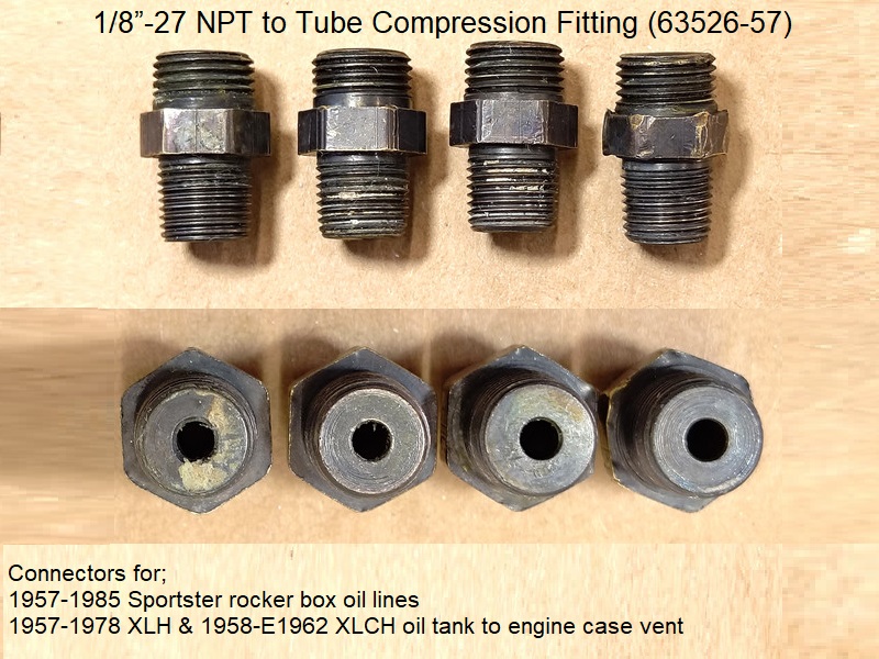 28)
28)
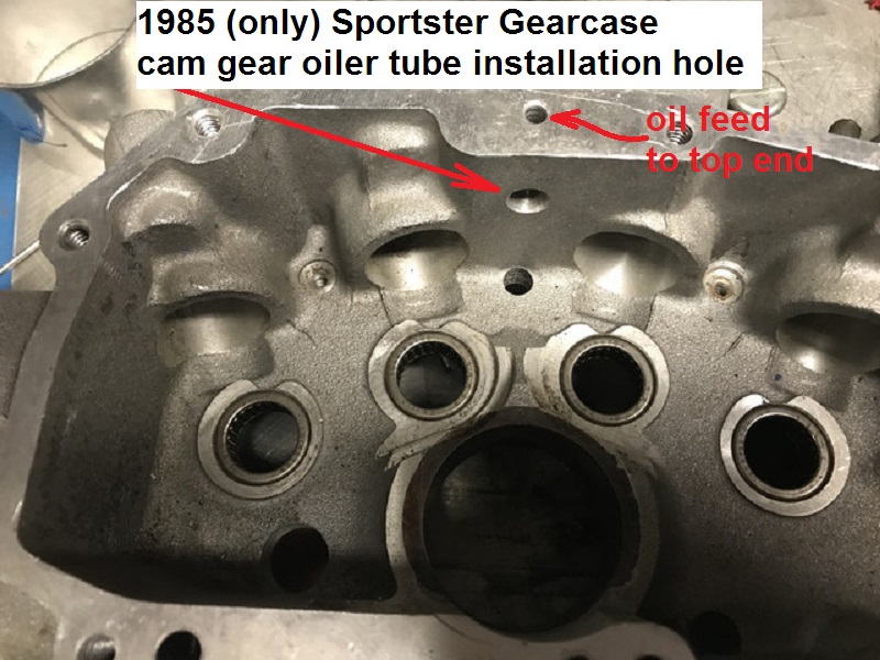
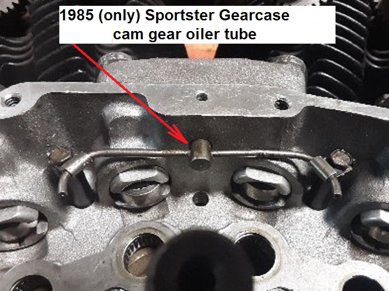
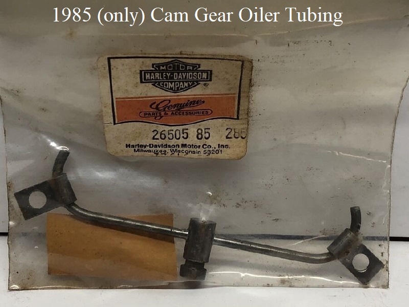
Cam Gear Oiler (1985 models only)
Starting with crankcase number 785 303 002, manufactured after October 29, 1984, a cam gear oiler was installed in the gearcase ceiling. 29)
Click Here to download Service Bulletin #M-899 for more details.
This is a one year only addition. In 1986, the MoCo deleted the tubing and installed a pressure bypass on the oil filter pad.
Then in 1992, they deleted the pressure bypass and simply drilled a .060” hole in the gearcase roof instead (similar to the 85 cam oiler system).
So the cam oiler tubing acts functions for cam lubrication as well as a high pressure release for the upper oil feed galley.
The cam gear oiler directs over-pressured oil from the upper feed galley to the gear mesh between the cams with 4 small holes in the tubing.
Direct lubrication of the gear teeth allows tighter gear fitment. Gear backlash and noise are reduced.
- The oiler tube has restricted orifices to spray the gears and still retain main oil feed pressure from whence the oil came (top oil feed galley).
- There is an O-ring on the oiler tube nipple that is pressed into the ceiling of the gearcase.
- If the O-ring fails to seal the oiler tube, feed oil pressure to the top end could be low.
Oil System Controls
Transfer Valve (76 and earlier)
Sub Documents
The transfer valve is not the crankcase vent (aka foo-foo valve). The crankcase vent fitting wasn't used until the 1977 model year.
It was installed in 77-78 engines only in the cam cover and vents crankcase pressure (air) to atmosphere.
Explanation for the foo-foo valve is here in the Sportsterpedia.
The transfer valve (25075-55) is installed in the left case between the primary and crankcase compartments. 33)
There is only one moving part in the transfer valve assembly which is the triangular shaped disc in the pics below.
Dims: The valve disc is a triangular piece of .009“ thick stainless steel that can move about .015” left to right in the valve assembly.
The ID of the thru hole of the assembly is .097“. 34) There is no spring to hold the disc to it's seat.
In a running engine, it is a one way valve that lets air and oil pass through it from primary case to flywheel case.
The video below was made by XLForum member, Harton, and shows how the transfer valve will move oil out of the primary into the crankcase.
But this is not indicative to true vacuum inside as the oil it's removing adds to engine vacuum until after the oil is removed. 35)
The source for transfer is not the valve but rather piston upstroke.
Positive crankcase pressure pushes the valve disc to the left and seals a small hole preventing flow into the primary.
Vacuum in the crankcase pulls the disc to the right up against a stop that has a larger hole.
The 3 cuts that make the disc a triangle shape allows air/oil to flow around it into the crankcase.
Without the engine running and with no spring to maintain a tight seal, oil can slowly leak through and let wet sumped oil pass into the primary.
On engine start up the excess oil in the primary should be transferred back into the engine.
The transfer valve is not the culprit in getting engine oil to the primary side. You have to remedy the problem at the oil pump. 36)
This valve largely seals by dynamic action (aka windage) from the down stoke of the pistons. The disk is only a marginal seal at static, and yes it will leak.
An engine will produce more HP if there is a slight vacuum in the crankcase as it does not have to over come pressure.
However, excess vacuum can cause problems in scavenging the oil from the crankcase.
This valve lets a controlled amount of air into the crankcase.
Crankcase vapor and oil is sent through the timed breather valve on downstroke along with any oil that has gotten over the disk level when parked.
The flow is not from the crankcase to the primary. There is no advantage to removing the transfer valve.
The transmission on the models that use it are designed for engine oil.
Blocking it and going with gear oil can cause problems down the road if your crankcase fills up with oil.
You can always tell when the crankcase has excess oil as the rear cylinder will usually smoke until the oil is scavenged out.
You can also notice a reluctance in the engine wanting to run up as it is churning all of that excess oil around draining off HP.
The excess oil in the primary will be scavenged back to the engine through this valve.
Note: on race engines, it is imperative to not allow oil to hit the crank and that is why windage trays and baffled oil pans are used.
Not only can it rob HP but it can also cause crank deflection and failure.
See Further Study of the Transfer Valve Operation and Affects of Plugging the Valve above.
The transfer valve is staked into position. 37)
Look very close around the edges and you'll see two spots that have been lightly punched.
The thread pattern is 3/4”-16. 40)
There is nothing to wear out. However anything that stops the movement of the reed (rust or dirt) means the valve won't work.
The one taken apart here was gummed up with old oil that had a tar like consistency.
Also, as a test, a container of 20w-50 oil at room temperature was allowed to gravity drain from the transfer valve.
It took 48 hours for 100 milliliters of oil to drip through the valve.
Here are a few drawings detailing the assembly:
Oil Pressure Switch
Sub Documents
See also in the REF section of the Sportsterpedia:
* Homemade Oil Pressure Light in case you don't have one.
* Testing the Oil Pressure Switch
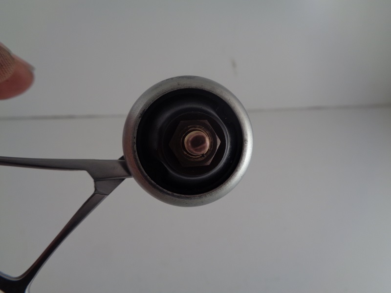
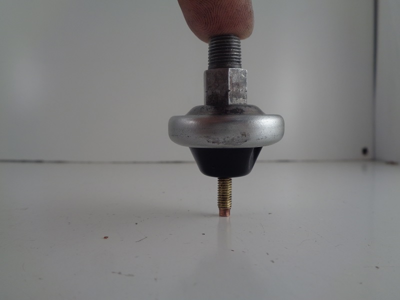
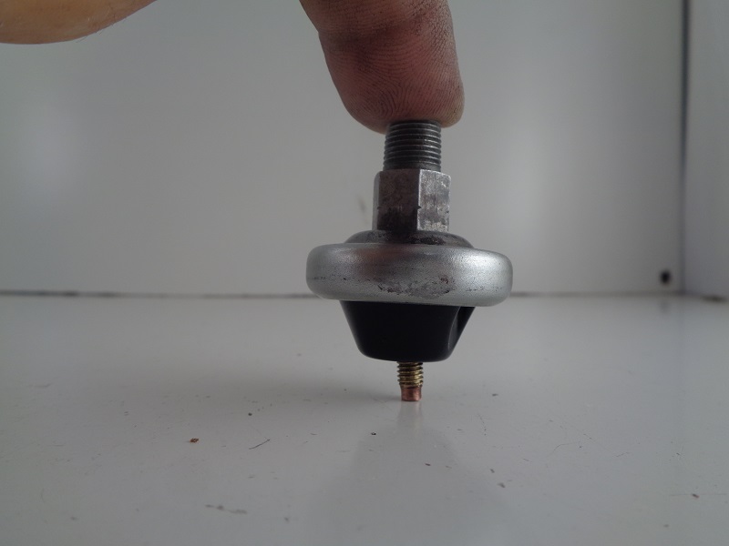
The oil pressure switch (for the oil light) is a pressure actuated diaphragm type on / off switch basically.
The diaphragm is spring loaded and held against it's contact point with the engine shut off or when oil pressure is too low while running (closed circuit).
When the engine is fired up, oil pressure builds in the oil pump and pushes the oil switch off it's contact point.
This opens ground to the switch and de-activates the oil light (open circuit).
Oil pressure is sensed by the oil pressure switch.
Thicker oil is harder for the oil pump to push thru the engine restrictions but the positive displacement oil pump keeps turning.
The combination of thicker oil (when cold) and constant addition of oil by the pump creates higher oil pressure inside the pump.
By the time the engine reaches over 1000 to 1200 rpms, the oil starts heating up and flows faster thru the engine restrictions.
The thinner, more free flowing, oil lowers oil pressure inside the oil pump (more flow means less oil backing up
the pressure).
The lower pressure allows the switch diaphragm spring to relax, moving the contact back toward it's seat (which could close the circuit / light the light again).
The oil check ball / check valve regulates a pocket in the oil pump to keep enough pressure in there to keep the light from coming on during operation.
Cold cranking oil pressure can reach between 30 PSI and upwards of 60-100+ PSI.
Oil pressure will vary from 4-15 PSI under normal riding conditions.
However, hot idle oil pressure will vary from 3-7 PSI.
So, at idle, the oil pump check valve is barely opened past it's cracking pressure (not to it's end of travel).
Oil Pressure Switch Pics
 |  |  |
 |  |  |
Oil Pump Check Valve
Sub Documents
See also in the Sportsterpedia;
Click Here to view Check Valve Dims.
The oil pump check valve plays a role in the operation of the oil pressure switch.
It adds additional restriction in the feed path which raises the oil pressure in the chamber feeding the switch.

The check valve is not a pass through but instead a cartridge type one way check valve operated by a spring loaded cup against a seat pressing at 4-6 PSI. Oil pressure enters the center of the check valve, lifts the cup against its spring and exits the check valve by pushing around and past the cup and into the engine. At a point, the cup will float off it's seat up against the spring towards the end of it's travel.
According to the FSM, the check valve has two main functions;
It prevents gravity oil drainage from the tank to the engine when not in operation.
It also acts as a restriction to activate the oil pressure switch.
Without the check valve, the pressure would not build up as much in the 'pocket' in the pump (see drawing above). It would free flow into the crankcase and disperse. With the check valve installed and the oil having to find it's way around the cup, pressure builds behind it in the pocket. This back pressure builds inside the pump and pushes the pressure switch contacts open, shutting off the oil light.
The check valve spring does not control the amount of oil that enters the engine (unless it's stuck closed). The flow goes past the check no matter what. The spring pressure is very light. It regulates (creates and manages) the oil pressure in the pocket next to the switch before it enters the engine. That pocket is protected for one reason (to operate the oil switch, therefore the oil light). If you are not running an oil light, there is no reason to be concerned with the check valve (in regards to a running engine). You could remove the light and the check and it would not affect the oil flow thru the engine. The positive displacement oil pump will still deliver oil.
The check/switch/light is a safety precaution to let you see the light and warn you that the pressure in the pocket is low.
In theory and design, if the pressure in the pocket is low, oil flow would also be low. In practice, there are too many variables on a worn engine,pump, check, switch etc. to keep theory and design true all the time.
The cup will stay off it's seat and open as long as there is sufficient oil pressure pushing against its spring. This spring actuates the 4-6 PSI pressure that the pump must overcome. If there is not enough oil pressure coming from the pump to keep the check valve cup completely or partially off it's seat; The back pressure from the spring will push the cup toward it's seat, or closed position, equal to the amount of minimum pressure loss from the pump. Thinner (hotter) oil flows faster and builds less pressure.
When the oil thins out, the oil pressure will still try to push past the cup. At a point, the pressure from the pump may not be sufficient to completely float the cup off it's seat. So, the cup will turn sideways a bit only allowing oil to pass it on one side.
This reduction in pressure is also sensed by the oil pressure switch. When the pressure drops, the diaphragm eases back toward the closed position. If the pressure is low enough, the contacts will close or partially make contact while closing or intermittently opening and closing. The oil light will come on or flicker depending on the action of the contacts.
The pressure switch requires no back pressure from the engine to stay open. It opens solely from the pressure generated from the oil pump with the assistance of the check valve to hold some of that pressure in the pump.
Rear Chain Oiler (1957-1976)
Sub Documents
The chain oiler is not part of the feed pressure system. It is tapped off the return oil system and is a designed leak to keep the chain from rusting up. There is a factory adjusting screw to control the amount of oil it gives. Return oil is tapped into to provide a drip for the chain. Due to it's nature, there will always be an oil leak from it. If you don't want the leak, you can try and tighten the adjusting screw. But chances are the screw or fitting itself has previously been tightened too much leading to an eternal leak.
Location:
The chain oiler fitting is either located behind the sprocket cover or at the oil tank respectively of year model and sometimes which tank you use.
- 1954-1966 KH, XL and XLH used a (63607-53) NPT x compression tubing x SAE threaded regulating fitting.
- 1958-1969 XLCH used a (63601-54) NPT x SAE x 1/4“ hose bibb regulating fitting mounted to the oil tank.
- (63611-53), chain oiler upper hose bracket mounts to the top of the case under the (R) motor mount bolt.
- (63612-53), chain oiler lower hose bracket mounts to the rear motor mount front right bolt to the case.
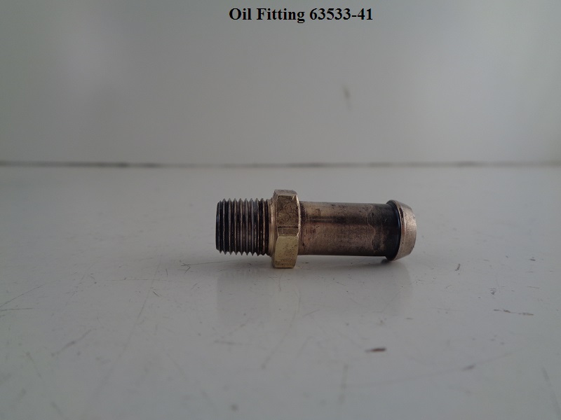
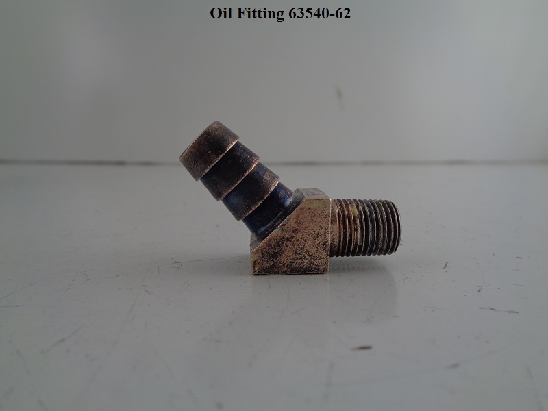
- 1967-E1972 XLH and 1970-E1972 XLCH used a (63595-67) hex body flared connection regulating fitting with a mounting tab to the top of the motor behind the rear sprocket.
- L1972-1976 XLH and XLCH used a (63595-72) updated hex body flared connection regulating fitting with a mounting tab to the top of the motor behind the rear sprocket.
Installed Pics:
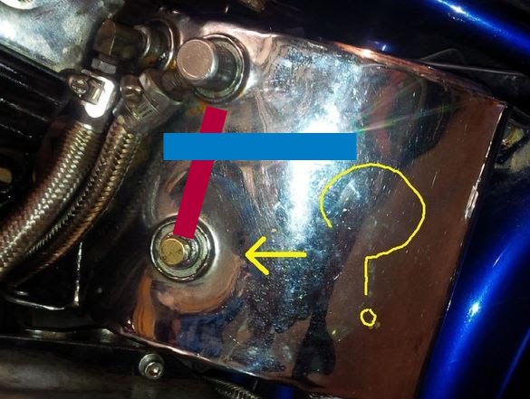
Below is a L1962-1965 XLCH “horseshoe” oil tank with an explanation of how the chain oiler gets it's oil.
The blue line is the oil level. The red line is a tube inside the tank. The bottom of that tube feeds the lower (chain oiler) fitting.
The top of the tube is open and above the oil level. So, nothing drains out of the bottom fitting if you open it.
Note the open top of red tube is directly below the return fitting.
When the bike is running, return oil spills into the red tube to supply the chain oiler fitting installed in the lower port.
This feeds chain only when the engine is running and doesn't leak when the bike is shut off.
 46)
46)
| Chain Oiler Piping on 74 XLCH 47) |
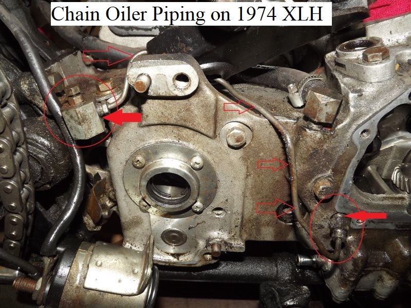 |
Oil Filter Mount
See also Remote Oil Filters in the REF section of the Sportsterpedia.
—– 1957-1978 XL - XLH Models —–
XLCH models did not have an oil filter.
XL / XLH models have a “drop in” oil filter mounted inside the oil tank.

—– 1979 Models —–
1979 models didn't come with an filter as a base sale from the MoCo.
However, an oil filter kit was debuted in 79 as an accessory item.
So some may have them and others may have not.
Oil filter mounting threads are M16 x 1.5mm. 50)
—– 1980-1981 Models —–
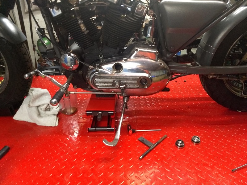
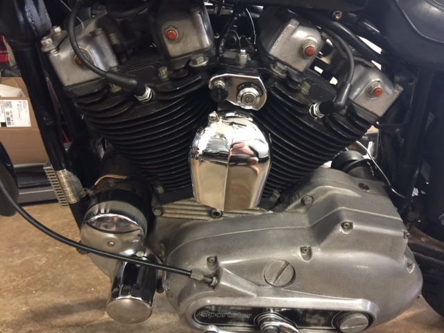
The oil filter was relocated on 1980 and up models and they were fitted with an external “spin-on” oil filter.
The filter mount is located on a bracket between the engine and the oil tank.
It's under the seat in a awkward place to work with. 51)
Oil filter mounting threads are M16 x 1.5mm. 52)
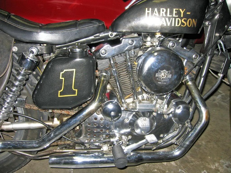
| Wide angle of filter location 53) |
 |
| Oil filter mount on 81 model. 54) The hooked hose fitting is connected to the oil return hose from the pump. The straight hose fitting in the middle goes to the oil tank. 55) |
|||
 |  |  |  |
—– 1982-E1984 Models —–
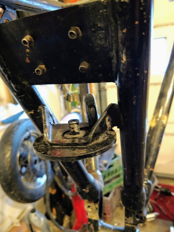
The filter mount is mounted on the lower left front engine mount.
This has also been a popular practice on earlier bikes.
| 82-E84 lower front motor mount / filter mount. 56) | |
 |  |
Oil filter mounting threads are M16 x 1.5mm. 57)
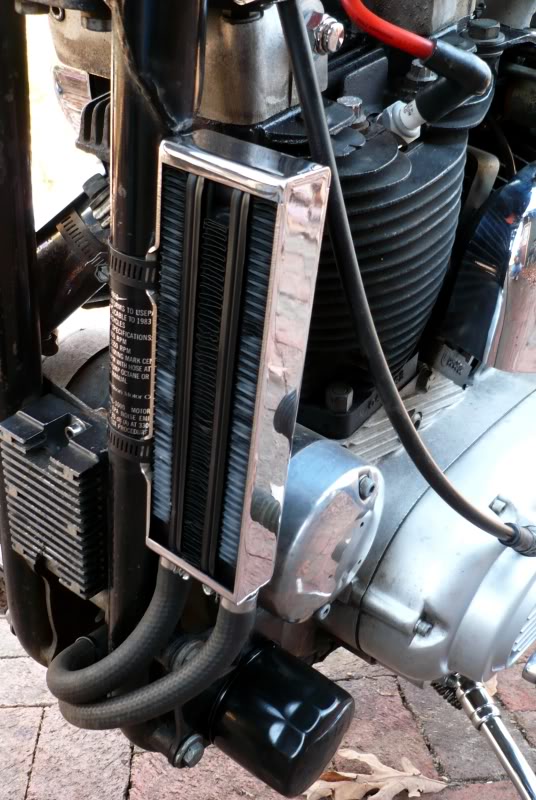
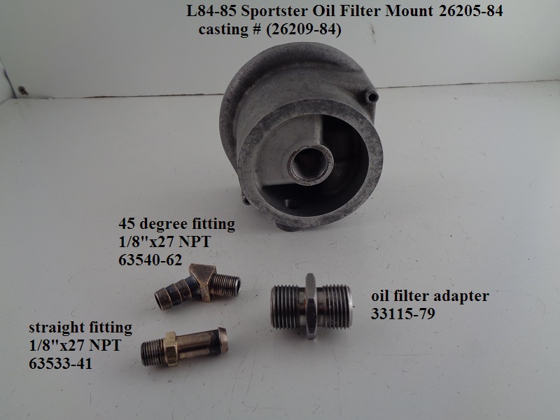
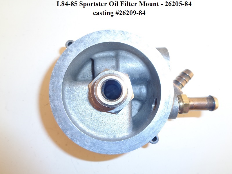
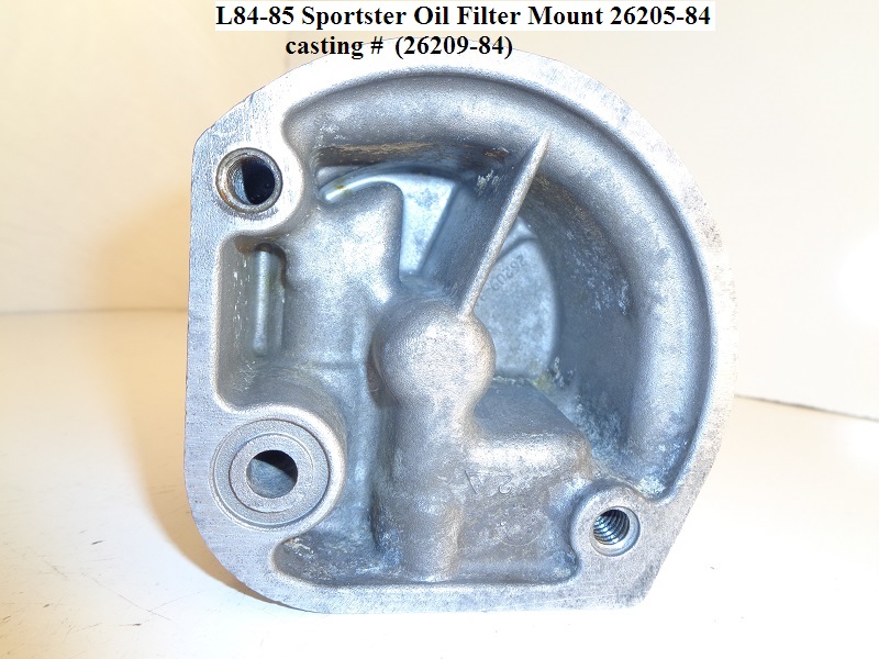
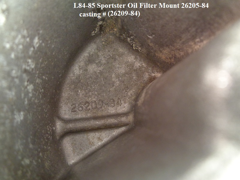
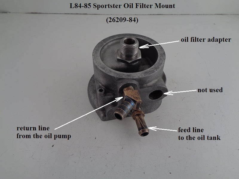
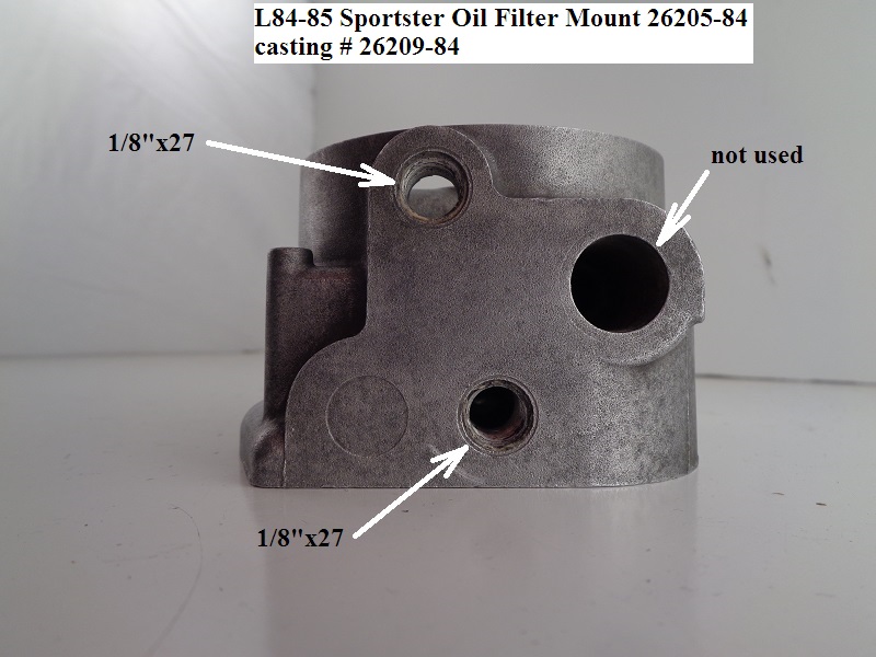
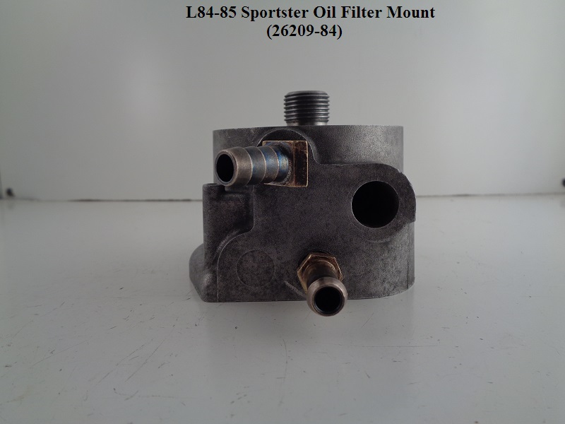
—– L1984-1985 Models —–
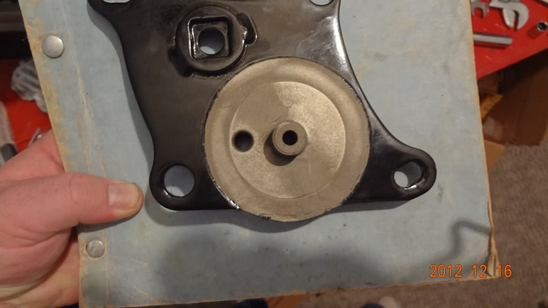
The oil filter on alternator ironheads is where the generator used to be. 60)
Two fittings (feed and return) are on the right case below the filter.
Room was made there due to the new alternator location.
This change was made along with the breather baffle tube assembly installed in the cam cover.
The oil slinger system was eliminated.
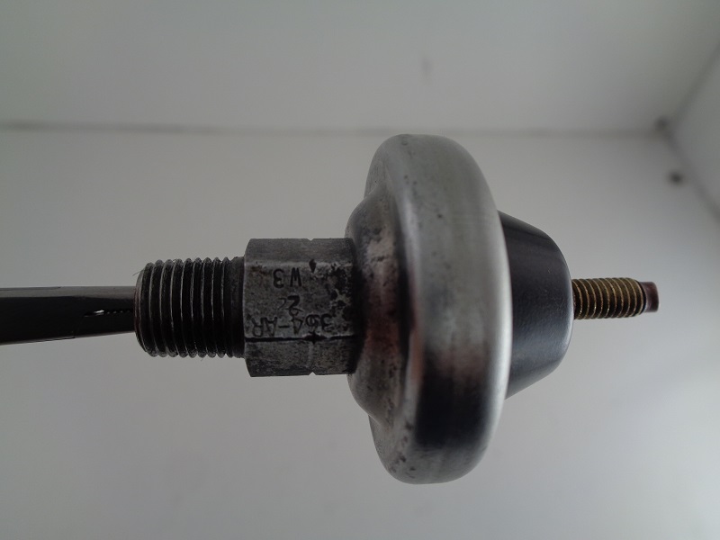
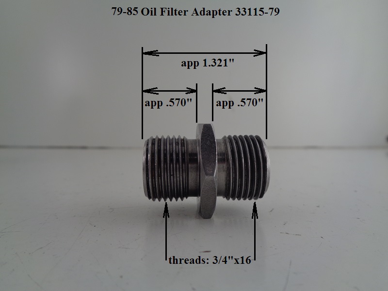
Oil filter mounting threads are 3/4”-16.
 |  |  |
 |  |  |
 |  |  |
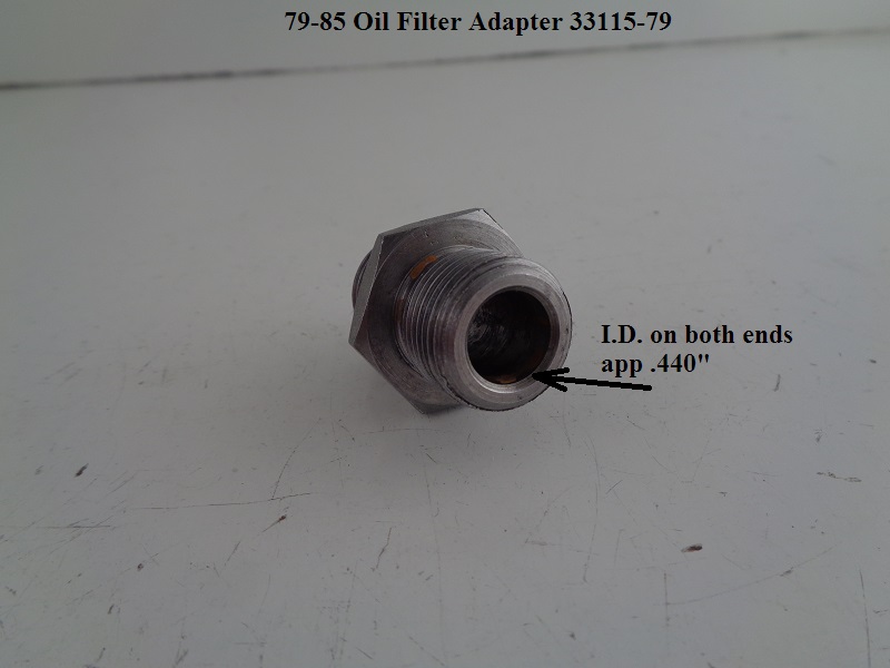
Oil Filter Adapter (L84-85)
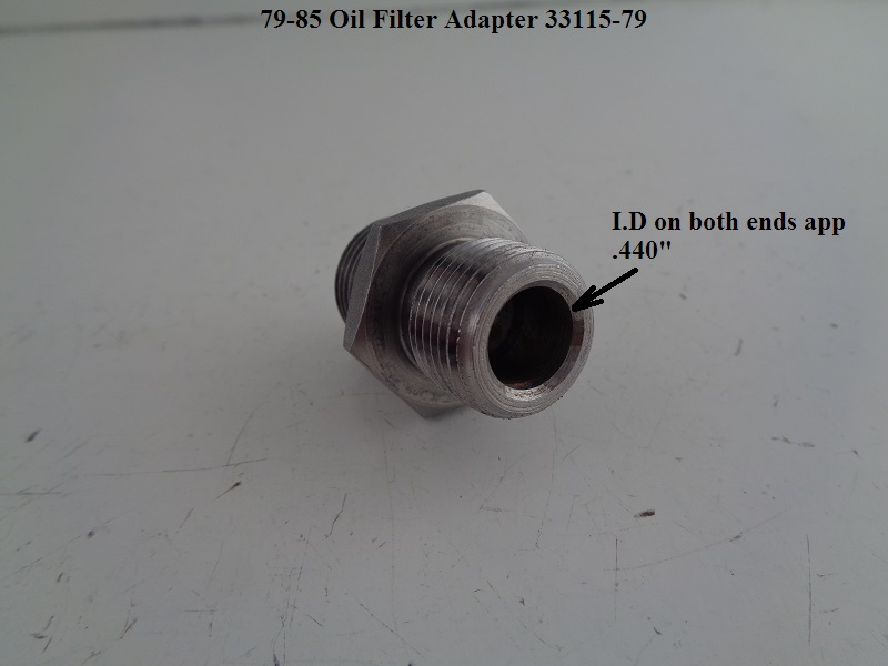
The threads on each end of the oil filter adapter are the same.
The I.D. on each end is also the same.
The adapter can be installed from either side as there is no check valve / check ball involved with the oil filter mount.
Installation:
Thread the adapter into the filter pad. No thread dressing is suggested by the FSM.
However, a light coat of anti-seize would protect the threads upon later removal of the adapter (if necessary).
Torque: 8-12 ft/lbs. 61)
Dims:
 |  |  |