Table of Contents

REF: Service Procedures 30
Testing the Oil Pressure Switch
In the Case of a Defective Oil Pump Switch
This switch opens and closes the contacts to the oil pressure light.
The oil light is important to have since if it is not working, it can be assumed that you have little to no oil flow to the engine.
If the pressure switch doesn't operate the light it should be checked for proper operation or replaced.
For the $30 or whatever you save by not buying the switch, it's just not worth it to not have the low engine pressure idiot light working. 1)
If your motor is ready to run and you need to test it then you can connect a piece of clear hose so you can see oil in it.
Don't plug the end till you've primed the pump (with ignition off kick it over a few times until oil comes out the clear pipe where the pressure switch lives).
Replace a defective switch as soon as possible.
- If the pressure switch is stuck in the closed position;
The circuit stays grounded with the engine running and the light stays on.
Hardened oil goop around the end of the switch can possibly block oil pressure from opening the switch. - If the pressure switch is stuck in the open position;
The circuit will stay open with the engine running or not.
The light will not come on during startup or alert you of low oil pressure during engine operation.
Testing for an Open Circuit
These were bench tested but can simulate conditions while installed with the signal wire removed.
This requires a multi-meter set for continuity with the buzzer.
The black probe below can alternately be placed against the engine.
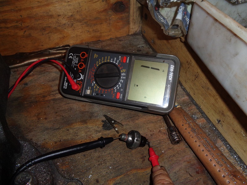
With the engine shut off and the signal wire dis-connected, the contact points should be pressing against each other ensuring continuity.
| Touch the probes on the same side of the switch to ensure you have good contact points on the probes. Clean the area if needed. | Probe each side of the switch and the buzzer on the meter should sound off thus ensuring continuity between the contacts. If not, the switch is defective and has to be replaced. |
 |  |
| This tested out to be defective with an open circuit. 2) | |
 |  |
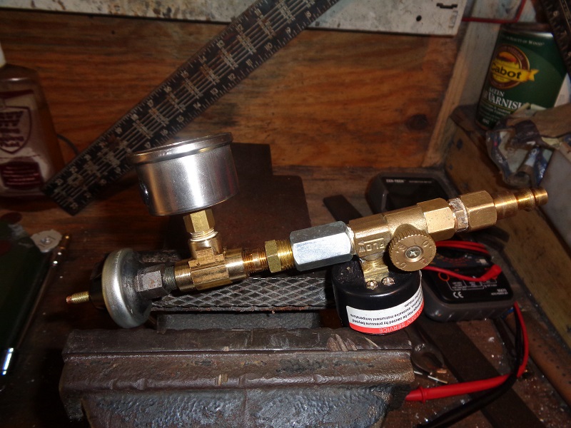
Testing for the Opening / Closing Pressure
This setup was made using regular plumbing and air hose fittings.
This requires a multi-meter set for continuity with the buzzer.
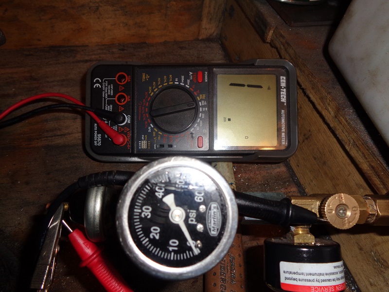
| The valve was placed inline in case something went wrong. 3) |
 |
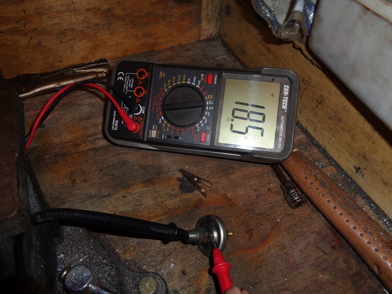
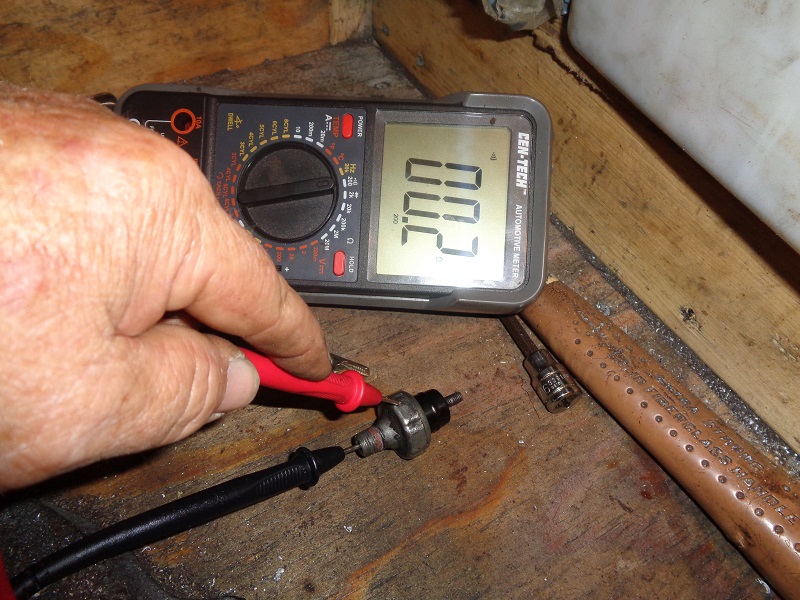
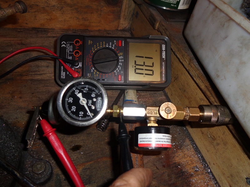
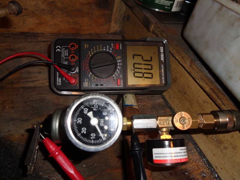
| With zero pressure applied, the circuit is closed, continuity is achieved between the probes and the buzzer sounds off. 4) | With 27 PSI applied, continuity is broken and the buzzer is quiet. 5) |
 | 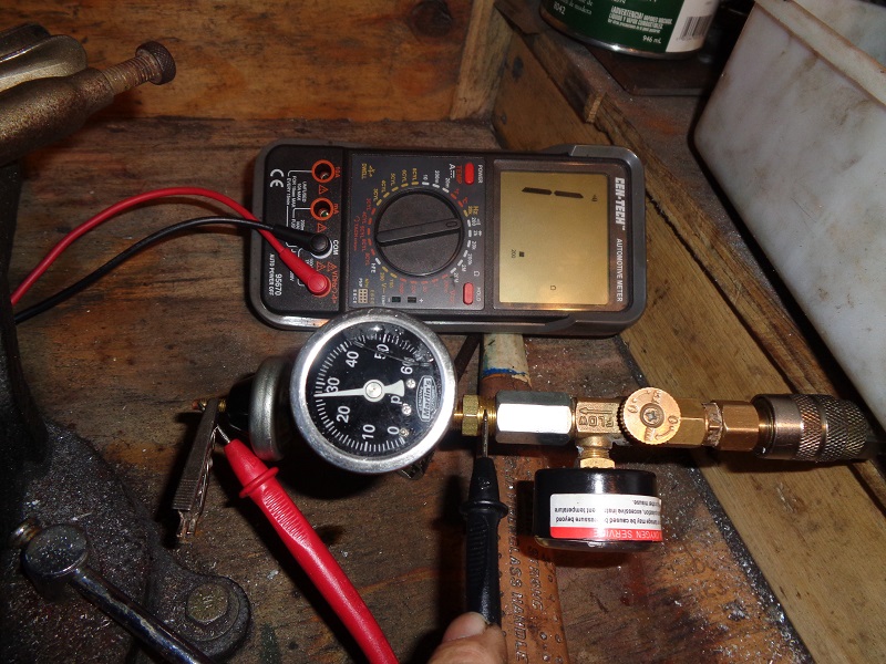 |
| This switch didn't make contact until the pressure got down to about 2-1/2 PSI. However, this test should have been performed with a lower range gauge for tighter low end calibration. 6) |
|
 |  |