Table of Contents
IH: Carburetor, Intake Manifold & Exhaust - Sub-01L
Rebuilding the Bendix Carb
See also in the Sportsterpedia:
Cleaning
- The general appearance of the inside of the carb is not necessarily a good indication of its condition.
It can look spotless and have clogged jets, or look cruddy and have clear jets. - It's good to clean each individual part rather than soak or boil the whole carb in carb cleaner.
But either way is good. Do not allow any solvents to contact any rubber parts (tip of needle, O-ring seal for bowl). - Make sure to take everything apart, jets, needle, accel pump, all rubber components especially.
- Examine all parts for excessive wear, damage, distortion, etc.
- Cleaning solutions/sprays vary based upon your location, needs, budget, preferences and quality.
Dismantle the carb down to the body before soaking. You will be surprised at all the dirt in the bottom of the soaking container.
Here are some helpful ideas:- An overnight soak in a solution of Pinesol and water followed up with a good brush down with a toothbrush then rinse and air dry. 1)
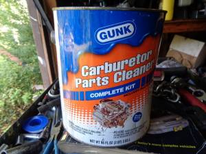
See also Soaking parts in the REF section of the Sportsterpedia. - A 20 minute to up to a few days soak in a gallon of Gunk (or other) Carburetor Cleaner that has a basket inside for small parts and lowers in the can with a handle, rinse, air dry, use.
- Soak it in mineral spirits for a few days. 2)
- You can use acrylic paint thinners for cleaning up carb parts. It melts the fuel varnish right off. 3)
- An aerosol spray carb cleaner will also work but may not loosen all of the build up in the jets or orifices in the carb body if they're not directly sprayed through.
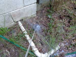
- Blow out all holes, jets and orifices thoroughly with compressed air after cleaning.
A gallon of carburetor cleaner is very useful in cleaning out varnish from the channels and metering chamber.
It is especially useful for soaking stuck gaskets between parts and loosen the joint between them for dis-assembly.
Depending on how old or how 'stuck' the parts are, soaking for a couple hours may help to separate the old gasket in between.
Make sure to remove any rubber or plastic parts before soaking. Also check the label for safety precautions.
Parts that have been sitting for years may have to be soaked for about 24 hours or even days.
| Carburetor Cleaner 4) | |
 |  |
Note:
The use of wire to 'rod' out jets and orifices is discouraged in the FSM.
However, a hard wire such as a welding tip cleaner, has been known to open up stubborn areas at times.
Always use a wire smaller than the orifice cleaned so you don't widen the holes.
Doing so could create burrs or change the hole sizes.
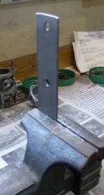
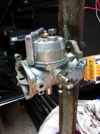
Carb Stand:
- You can put the carb in a vice to remove the screws, and for much of the following work.
Wrap in a shop towel; close the vice gently taking extra care with the choke and throttle linkages.
The vice is a needed extra pair of hands. - It can be very confusing trying to decide which way to bend the tang if it is not correct.
If the fuel level is low,Is the float high or low?, Do you need to bend the tang up or down? etc.
On the bench the carb is usually upside down, adding to the confusion. You should sort all this out before making an adjustments.
However, this setup works better than putting the carb directly into the vice.
The carb is set upright as 'in use' making adjustments more straight forward.
 5)
5)
 6)
6)
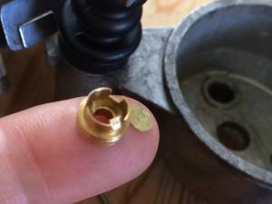
Welch Plug or Expansion Plug
- Inspection:
- A close inspection around the walls of a welch plug can reveal possible leaks.
- Removal: 7)
- Whenever a welsh plug is removed, a new one should be installed in it's place, especially since a large part of the time, removal of one means destroying or deforming it.8)
- Drill an 1/8“ hole thru it (just deep enough to break thru to the other side) off center and pry it out with a small punch. Be careful not to drill too deep which could destroy the nozzle assembly or casting. While prying it out, be careful not to damage the casting counter-bore edges around the plug.
- You can also drill a small hole in it and use a small tap just big enough to start in the hole. 9)
Thread the tap in the hole.
When it gets to the bottom of the passage, it will force the valve out with out damaging the bottom of carb passage.
Make sure to clean all the chips out to keep from plugging up passages later.
-
- The plug should be seated with a flat end punch that is slightly smaller than the diameter of the plug. The plug should be flat and not concaved to assure a tight fit. If leakage is suspected due to a rough or damaged welch plug seat in the casting, apply a small amount of epoxy or suitable sealant to the edges after installing it.
Links to Welch plug sites:
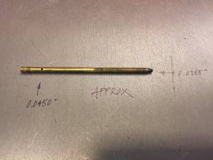
Idle Tube
Check the idle tube for cracks (fixed or adjustable). The fixed tube below doesn't look cracked unless you look at it close up.
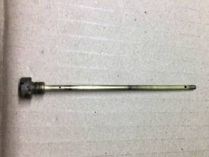 12)
12) 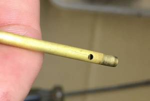 13)
13)
Check that the idle tube lands in the center of the bore in the carb. 14)
Check that the tube isn't cross threaded or bent.
It has to seat in the middle of the main jet discharge tube (or be allowed to pull into the main jet as to have wiggle room).
The main jet will straighten some as puts in back in line when it's installed. If it doesn't, replace it or it'll cause problems.
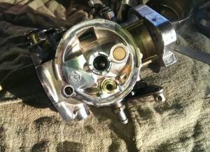 15)
15) 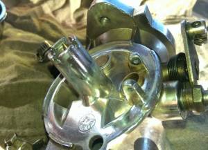 16)
16)
A sealed tube replacement can be found here at Biker Directon the net but it doesn't give the jet size but only the length: 3-1/8”.
Part Number: 35-0533, Manufacturer: Bendix
 17)
17)
Float
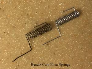
Inspect the float spring. It should not be stretched or distorted.
Inspect the needle valve cone point for wear and scratches.
Setting the float level
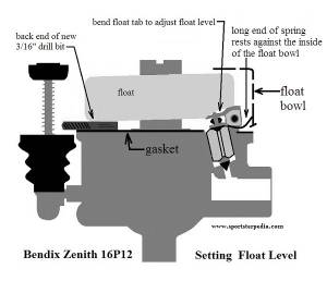
With the carb upside down (needle valve seated) the bottom of the float should be 3/16“ from the gasket at a point opposite the hinge. 18)
You can insert the back end of a (new or clean / non distorted) 3/16” drill bit under the float as a guide for this measurement.
It's been debated whether this measurement be made with or without the gasket since the thickness of different gaskets can vary.
And there are also variances of aftermarket needle valves or condition of the used one as well as valve seat conditions to consider.
So you may have to adjust a bit to get the right setting.
Use needle nose pliers to bend the tang up or down as needed to;
(1) allow the float to sit on top of the drill bit (2) at the same time the valve is lightly seated.
Note:
Very minute adjustments add up to a lot of difference in height. 19)
Setting the float with the gasket on or off has been disputed when using the 3/16“ drill bit measurement. 20)
Some say it makes more sense to take the measurement without the gasket.
Sensible argument A: gaskets vary in thickness and if the gasket is used, will be further compressed.
Sensible argument B: How accurate does it really need to be?
Carefully guide the cup of the accelerator pump into the pump well. Seat the accelerator pump boot around the top it's pump boss.
Assemble the fiber washer and O-ring on the main jet. Install the float bowl taking care to get the spring between the carb and bowl as in below .
Install the main jet snug, plus a little. Don't over tighten.
Installing the Float Spring
There have been several explanations of how the spring operates and it's positioning.
Most notably:
- The spring is there to help lift the float. When the float drops down the coil is wound up tighter.
- The spring is there to force the float away from the needle towards the bottom of the bowl.
This prevents the needle sticking in position and stopping or restricting fuel flow into the bowl. - The spring makes no difference in operation so just remove it.
While there are really good arguments for each of these, you must decide if you want to use the spring and how to attach it.
If you choose to use the spring;
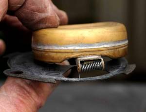
The correct procedure for mounting the bowl with relation to the float axle spring that is often asked is this: 23) 24)
Hold carburetor inverted (upside down) and rotate the long end of float spring up towards float.
Position the float body carefully while keeping the long end of spring pushed to float.
Slide body on slowly as far as you can while still keeping spring end pushed back until you can release it.
(so it contacts/presses the inside wall of the float bowl)
Now push the bowl all the way on. The spring should not be between the gasket surfaces between carb body and float bowl.
It should be inside the carburetor completely against the inside wall of the float bowl.
Remove the main fuel jet and tube assembly to reveal the float assembly.
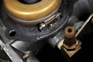
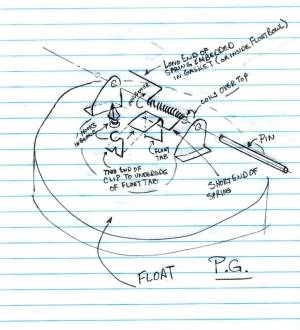
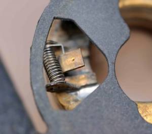
Note: In the pic below, the float spring's long end is stuck embedded in the gasket. 25)
This is the wrong way to do it, although the carb was ran for years with it like this. 26)
The short end of the spring goes underneath the tab on the float.
This is another difference from the factory manual.
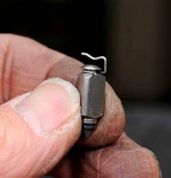
The needle in this carb has a groove around the top of it where the one depicted in the manual has a hole through it.
This clip fits around the needle resting in the groove and the factory clip is different as it goes through the hole.
So which ever set up your carb has, both do the same thing (connect the needle and float) but do that differently mechanically speaking.
To assemble the needle, clip to the float first locate the spring, getting the short end under the float tab. Then attach the needle and clip.
The correct way to install the spring is with that long end up against the inside wall of the float bowl.
Look at the spring and notice how the spring coils are wound in a certain direction.
If you lift the long end up and place it inside the float bowl wall as you slip on the float bowl you will have done it correctly.
This will actually coil the spring tighter and you can easily see that looking at how the spring is wound.
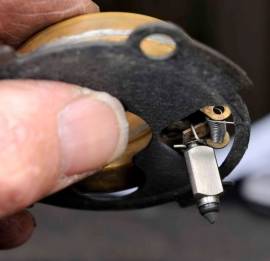
In the pic to the right, the needle has the clip attached and the top of the clip slides on top of the float tab. The needle is just hanging there.
The float spring long arm is in the foreground and is still embedded in the gasket.
At the spring's far end is the short end of the spring and that short end is under the float tab.
Before reinstalling the carb on the bike, a scribe was used to lift the long spring end upwards off the gasket and tuck it inside the bowl as the bowl was installed.
This is the position it should be in officially. Resting against the inside wall of the float bowl.
As you lower the float bowl down, just use a scribe to lift the long end of the spring up inside the bowl and let the bowl come down.
All this is done with the carb upside down also.
This entire assembly is now ready to be lowered down onto the carb body (once the float pin goes in of course)
You can use a fine scribe to guide the float needle into is resting spot and to align the float flange holes, spring holes etc. Do it gently.
You set the correct float level to 3/16” by gently bending the float tang. The float tang is the piece of metal that touches the bottom of the float needle. 33)
You use a drill bit placed under the float opposite the side where the pivot pin is located.
You can check the float level by removing the float bowl and turning it upside down. The float will now close the needle when you invert the carb.
On the side of the float, opposite the float pin location, slide a 3/16“ drill bit under the float.
If it just slides under, then the float level is correct.
If it won't slide under, then the float level is too low.
If the drill bit goes under the float but the float is higher (daylight between the drill bit and the float) then the float level is too high.
Test "to assist in opening the float needle"
To confirm the spring is installed to assist in opening the float and needle, you can do this test.
Assemble the float & spring.
- Hold the carb sideways.
The carb below is mounted on it's side, leaning off center to the left. This was done intentionally. - With your finger, press the float closed & released.
- When the float opens, it will move to the right, past center.
(if the spring is installed wrong, gravity & the spring would have kept the float leaning to left of center.)
Here is a short video showing the spring action 37)
It would appear the spring has too much tension, but it's actually not.
Here's another short video showing the spring action when submerged 38)
Here's the last video with the above test performed and the carb worked afterwards. 39)
Accelerator Pump
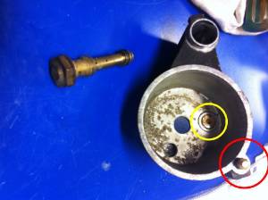
Check valve
Check the accelerator pump circuit to make sure it's clear.
If there is a clog, it could be a stopped up nozzle (red circle), check valve (yellow circle) or possibly both. 40)
You can try to clear it out by using compressed air (in the reverse flow direction) to attempt to clear the nozzle.
Then try a blow test (aka mouth on the accelerator pump cavity & a finger blocking the nozzle) to verify the proper check valve operation.
If the check valve is mal-functioning, air (air in this test, gas in real life) will feed back into the carb bowl vs going out the nozzle.
If it be necessary to remove the check valve, that can be done with a pair of needle nose pliers.
The replacement check should be installed with a flat faced drift / punch sized just shy of the OD of the check valve. 41)
Be sure the tool used to install it is bigger then the ID. If not, it can slip down and punch the disc out of the check body (as in the pic to the right below).
If this happens, the check function is lost and the valve assembly has to be replaced.
The check valve seals off the main fuel supply between the bowl and the accel pump passage when the pump is actuated.
So if the check isn't working, it'll squirt gas into the bowl instead of the venturi.
To be sure the check valve is working;
You may be able to add gas to the bowl (bowl removed from body), and work the pump shaft by hand to see if it squirts gas into the bowl or the nozzle.
You should also be able to block the nozzle (not the check hole) and Not see any gas shoot up into the bowl but rather out the accel pump shaft housing.
Pump diaphragm
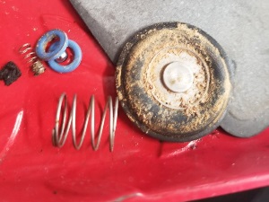
Clean and inspect the diaphragm for pinholes, cracks, rips, deformation, gunked up rust or varnish deposits and etc. Replace the diaphragm if necessary. 44) Residue from dried ethanol can result in a gunked up diaphragm as it if left long enough to separate from the gasoline. 45)
Accelerator pump shaft
Inspect the accelerator pump rod for bending. Inspect the rubber boot for cracks / tears. Any dirt that gets past the boot into the accelerator pump passage should be blown out from the side opposite of the nozzle (or check valve will close, making cleaning impossible).
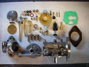
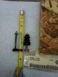
If you placed the plunger in the Taiwanese rebuild kit next to the stock part, the Taiwanese part is much longer. 46) →
This in turn can cause the plunger to 'bottom' in the bowl and it can get stuck as in when at W.O.T.
It actually can bottom before the butterfly is fully opened.
You can use most of the parts in this kit but purchase the Harley Part (#27762-71TA).
Aftermarket rebuild kit:
There are 3 holes in the accelerator pump shaft to provide more or less fuel upon acceleration.
Install the pump shaft pin in the bottom hole for richest setting or the top hole for the leanest setting.
In some of the new kits, you may find the accelerator pump is slightly too long as in the pic below. 47)
The throttle could hang up at about 90% (the bracket mechanism might hang up on the shaft, if the shaft is too long).
Fortunately the solution is fairly simply. Take a dremel tool and trim the top about 1/16” - 1/8“ or so and bevel the edges.
Click on a pic to enlarge:
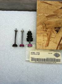
In the first pic below, the left one below is the original accelerator pump as it came from the factory in 1974.
Middle is from the new rebuild kit. On the right, is the accelerator pump (27762-71TA) as purchased from a local HD dealer.
The middle unit is the problem item. The upper section, the piece above the roll pin, is too long.
The second pic below is the after pic. The middle unit, has had the upper section of the shaft trimmed down. Good to go now.
Rub some oil onto the umbrella before installing it. 50)
This makes sure it sets itself instead of binding / deforming in the first few uses (also insures smooth operation).
Also look down inside the bore of the acc pump and make sure there isn't any residue scale.
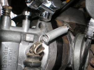
Add this spring to your accelerator pump if you don't have it. It will pull the butterfly closed when you let off and give the throttle a good feel.
 53)
53)
Carb Flange
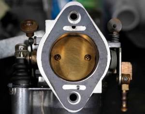
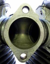
There are 2 small holes in the carb to manifold flange (as viewed on the outside).
Those holes are factory drilled as part of the manufacturing process and serve no further purpose. 54)
When mounted against the manifold, they would be blocked anyway.
The small hole was used for cross drilling the air runner boss then through drilled from the top of body for the idle mixture screw.
Some flange gaskets have cutouts for these holes and some do not. Don't worry about them as you can use either gasket. 55)
The gasket producer more than likely had a carb body to use for a guide when making the gaskets.
Adjustable main jet conversion
Some say not to do this as an adjustable main jet is too easy to inadvertently lean out the mix too much and burn a piston or two. 58)
If your certain carb is suppose to have a fixed jet but has an adjustable jet instead, it may have been modded for the adjustable jet.
For the adjustable main jet modification, the kit describes cutting a thread in the hole where the welch plug normally goes. 59)
J&P sells the conversion kit. Adjustable Main Jet Kit for Bendix/Zenith Carbs
J&P Cycles Part Number: 401-817, Manufacturer Part Number: 35-0202
- Establishes full adjustability for Bendix and Zenith carb main and idle circuits
- No need to stock several and expensive fixed jets
- Requires special tap 400-966 for installation
- Kit includes main jet, fiber washers, idle jet and control spring
Installing the Adjustable Main Jet Kit
J&P sells the conversion kit. Adjustable Main Jet Kit for Bendix/Zenith Carbs ($65)
J&P Cycles Part Number: 401-817, Manufacturer Part Number: 35-0202
PDF instructions are here.
The tap that is required for this conversion (9/32″-32 tapered) does not come with the kit. It has to be purchased separately.
J&P also sells the tap V-Twin Manufacturing Adjustable Main Jet Kit Installation Tap ($80)
J&P Cycles Part Number: 400-966, Manufacturer Part Number: 16-0865
Note: You can also search machinist supply stores online to get it a cheaper price.
The instructions say that if you have the (72-74) model with the screw in fixed jet, you can tap the carb 'on bike'.
However, it's always a good idea to remove the carb when it's possible to get tapping chips into the passageways so you can blow it all out when done.
- Remove the main jet from the bottom of the carb and the idle tube from the top.
If your idle tube is under a welch plug, you'll have to remove it to get the idle tube out.
See also Welch Plug or Expansion Plug in the Sportsterpedia for removal and installation of a new plug.
The instructions that come with the kit say to remove the bowl and use a drift to knock the tube out the top carrying the welch plug with it. - The hole is already the right pre-drill size for the 9/32″-32 tap.
Lube the tap with water or gas and carefully run it into the hole. Turn in 1/4-1/2 turns, back it out, clean the chips and go back in until the threads are cut.
Then blow out all chips / debris with compressed air making sure it's all clean inside. - Install the bowl and main jet into the bottom of the carb. Make sure the gasket, washer and O-ring are in place.
- Install the adjustable idle tube and spring in the top of the carb.
Initial settings:
Low speed needle:
Turned in (clockwise) will lean the mixture.
Turned out (counter-clockwise) will richen the mixture.
The needle valve is held in position by a spring.
Adjustment:
Turn low speed mixture screw all the way in (clockwise) until lightly seated (do not tighten).
Then back it out (counter-clockwise) app. 1 full turn.
High speed needle:
Turn high speed mixture screw all the way in (clockwise) until lightly seated (do not tighten).
Then back it out (counter-clockwise) app. 4 full turn.
The closed position of the needle will be when the individual coil springs are snug).
You should now be able to start the engine and do the final tuning.
Idle speed.
Set the idle speed with the throttle lever stop screw:
Adjust stop screw to the engine idle at desired speed with the throttle fully closed.
(Clockwise makes engine run faster, counterclockwise makes engine run slower.
Never set idle adjustment to slowest possible speed.
An extremely slow idle causes bearing wear, oil consumption and slow speed acceleration problems.
Final adjustments:
Make final low speed needle adjustment after engine is at operating temperature first in then out to see if the engine picks up smoothly.
Starting and all around operation will be better when the mixture is slightly rich.
If necessary, go back to the idle stop screw and readjust, then back to the low speed needle.
During high speed operation, the fuel is metered by the adjustable jet.
With the idle speed and mixture settings complete, high speed mixture is set by running the bike up to 4500 or more RPM.
If the mixture is too rich, the motor will break up / run rough.
To lean out the main jet, turn the main jet adjustment needle in about 1/2 turn at a time until the engine pulls thru high RPM in 1st and 2nd gear.
After you've set the high speed mix, you nay have to slightly re-adjust the idle mix.
When assembled, look at where the idle tube “adjustable main jet” touches the mainjet body. 60)
By looking into the carb throat, they never go straight down the middle.
Now look at the idle fuel tube and index so that none of the holes in the idle circuit tube are in contact with the mainjet body.
Once you figure out where the holes are in the idle tube, you can make 1/2 turns till proper main adjustment is achieved.
If you stop with the holes covered it will run like crap.
Bendix / Zenith Manuals and Other Helpful Links
Zenith Fuel Systems:
Replacement idle tubes:

