Table of Contents
This is an old revision of the document!

IH: Oiling & Lubrication - Sub-03G
57-76 Oil Pump Damage and Repair
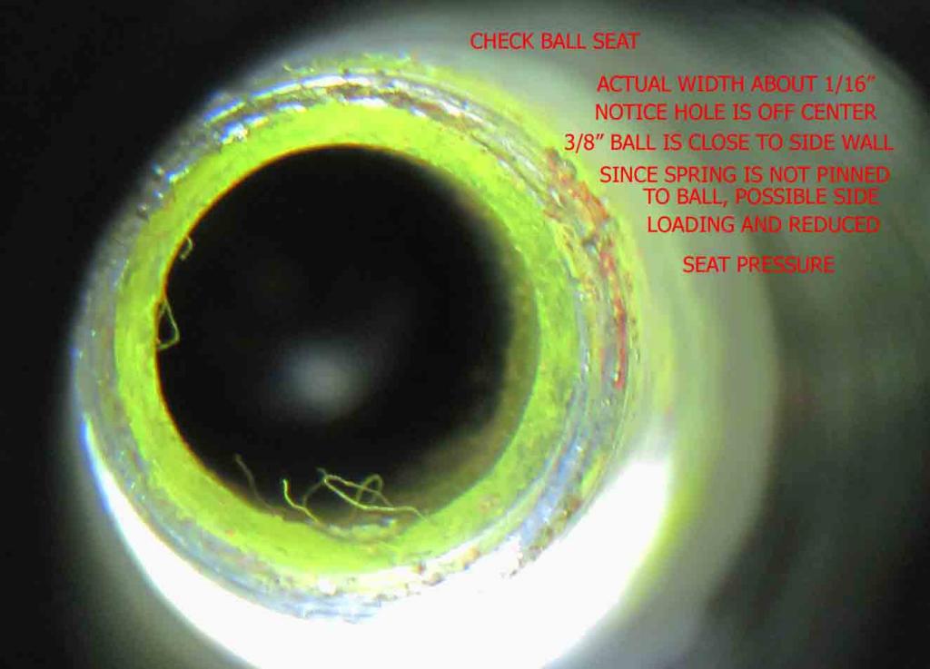
Check Ball Seat Repair
Below are a collection of fixes and ideas for repairing the check ball seat from the XLForum.
The design of the oil pump for our beloved IH's is perhaps, a little rudimentary. 1)
They work well enough for most situations but do have one annoying habit. They tend to leak like a sieve. They leak on the inside.
This leak leads to what we know as “wet sumping”. This is normally nothing more than a pain in the proverbial…
But in some circumstances it can be a headache.
Some engines never had the holes drilled and tapped for the sump plug and some people never pull the sump plugs out for fear of damaging the threads.
When your engine does wet sump, it can make it much harder to kick it over. On a stroker burning Methanol it just makes it nearly impossible.
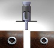
The oil drains down from the tank into the feed section. The shaft comes through the bottom of the pump tower.
And the clearance between the hole in the pump tower and the shaft is where the oil gets past.
By bustert
See also bustert's videos on YouTube:
- Youtube video on an oil feed seal. Far easier and non destructive. 3)
 |  | 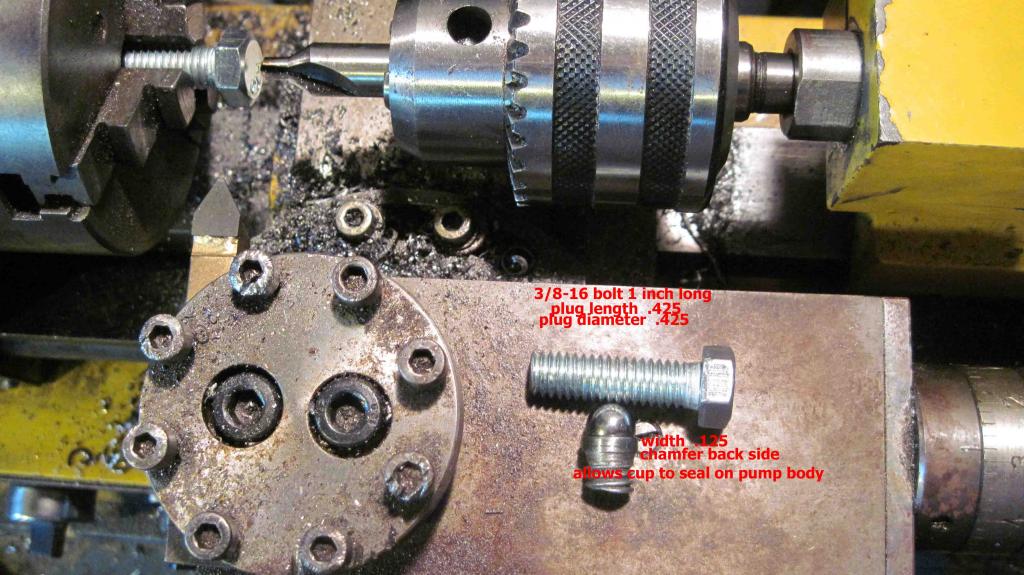 |
Here's another idea:
Normally, you'd use precision equipment for this. However, below shows how you can do the job with common home tools.
The cost of this project would be $4.00 U.S. for the bushing and whatever you can find a milling bit for.
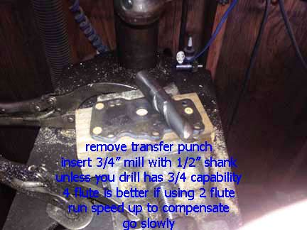
Done with a 1/2“ shank because most will not have a 3/4” capacity chuck.
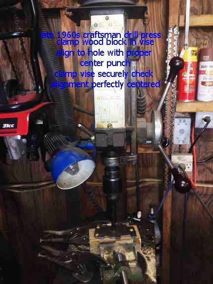
The late 1960s Craftsman in the jpeg below has 5/8“ capacity and is the original. The quill is still tight so accuracy is close enough.
As with any boring, keep the work as close as you can.
The 4 fluke would be better but if you speed up the drill, then it compensates, just go slow with lube so no chatter is induced.
The process:
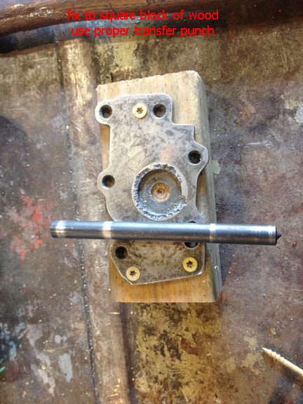
- Square a block of wood thick enough to fit the vise and allow the extension to fit without bottoming out.
- Attach the upper plate to the wood block with tapered head screws to prevent movement.
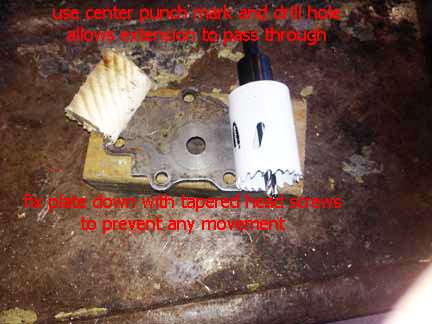
- Use a transfer punch of proper size and mark the wood block, remove upper plate.
- Bore out proper size plug and insert the upper plate extension into the hole and fix with tapered head screws to prevent movement.
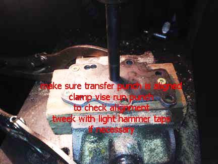
- Fix block of wood to vise and use proper size transfer punch to align to the quill.
Clamp vise securely and make sure punch is center and moves freely. If needed, tweaks can be made by sight taps to the vise. - Now you can slowly mill the hole. Take your time as the plate is cast steel.
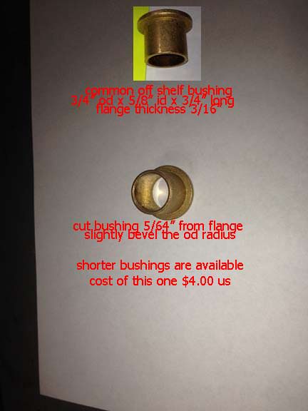
Now you have the hole. The bushing needs to be sized but you can find shorter lengths.
Now from the bottom of the flange, measure up 5/64” and cut the bushing and round off the radius to ease installation, just the very edge.
Do not get into the seating area.
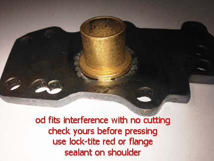
Once this is done, place the upper plate on a block of wood with a 3/4“ hole drilled in it to support the plate when installing the bushing.
Make sure it is squeaky clean, add red Loctite or flange/bushing sealant to the underside of flange, install into the hole and let it set up.
As an option, you can slightly run a taper drift into the bottom side of the bushing and slightly taper out the hole to add more interference fit IF you want, the sealant should be enough to cement the bushing. now dress off the bushing flat to the plate and you are good to go.
Now all you do is insert the seal into the bottom of the bushing cup side down till flush.
These plates with extension can be made from regular steel and tubing.
By Ferrous Head
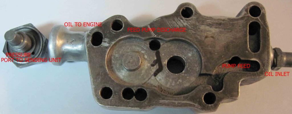
The pump already has an oil seal in the body of the pump.
This seal stops oil from leaking past the shaft on the scavenge side and into the feed side gears.
What HD didn't do was use an oil seal above the feed gears to stop oil leaking past the shaft into the pump tower.
So the shaft itself just runs against the cast iron pump tower until it wears enough clearance for itself to not interfere with the oils passage.
Once that happens the pump will leak.
With the bike leaned on it's kick stand, the oil leaks into the sump and then overflows into the primary case via the oil transfer valve in the left case half.
This really is a design flaw and should have never been allowed to persist.
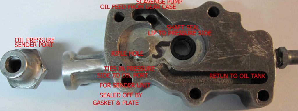
This solution is to install a seal in the pump tower.
The biggest problem here is the area that should hold the seal is only about 3mm thick.
And the answer to that problem is to machine up a “top hat” to be pressed into the pump tower to hold the seal.
The seal used is the same seal used in the pump body (26227-58), about $4 worth.
The machining was farmed out to a local shop. It took them 1/2 hour to make two top hats, machine the towers and press in the top hats.
They also made two tools for the installation. Both tools are very simple for anyone with a lathe to make.
The first is a backing tool that stops the pump tower face from distorting (bending inwards) when the top hat is pressed into place.
The second is a seal installer. However, it can be dome without the seal installer.
After the top hat is pressed into place, the pump tower face is faced off.
So, $55 for the machine work and $8 for two seals.
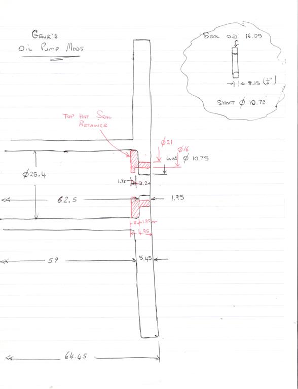
Below is a sketch of the top hat. The measurements are metric but can asily be converted to inches.
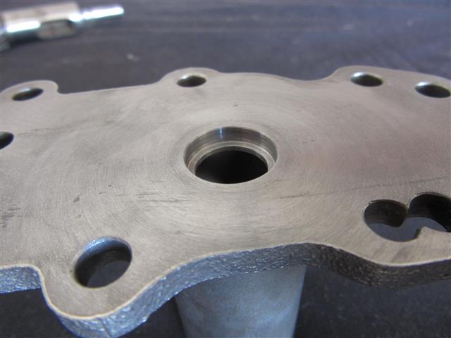
The machined tower with the hat already pressed in is to the right.
It should be clear to your machinist what is required from this. The actual line between the pump itself and the top hat is hard to see but it is there.
Click on a pic to enlarge.
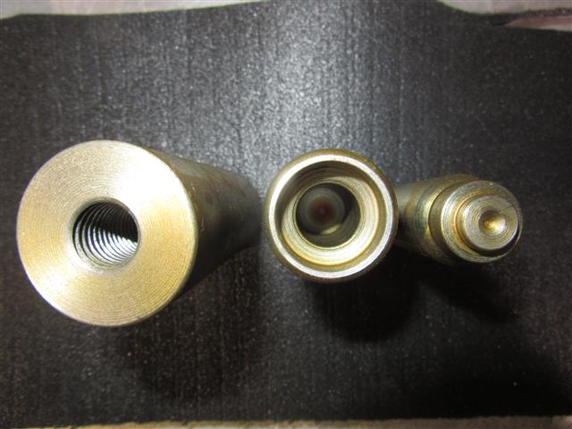
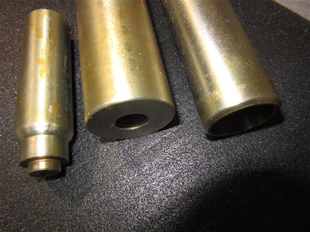
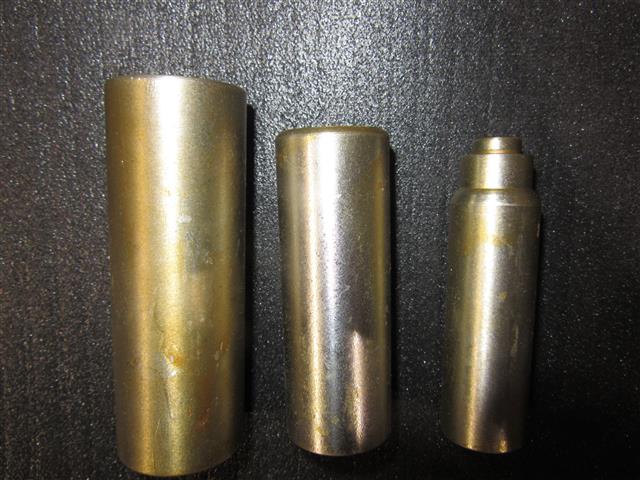
Here are pics of the tools (made from mild steel) that were made for installation.
They are coated them with Soft Seal to keep them from rusting while waiting to be used.
As you can see, they are quite simple and can be made in a few minutes by a competent machinist.
One is used as “backing” or the pump tower when your installing the top hat.
The pump cover is only about 3mm thick and you could bend it when your installing the top hat.
Also below is the tool to install the oil seal. Not really necessary but it makes the whole job faster and easier to do.
By needspeed
When the pump is together there is a 3/16” space between the bottom of the breather sleeve and the top cover.
Enough room for a 1/8“ thick insert that holds the seal and is tight to the I.D. of the cover tube.
It has a relief cut to clear any radius or chamfer that sometimes is left at the bottom of the hole.
It also makes a space for any excess sealer that could be used. There are no mods to any part of the pump.
This was made from aluminum on a lathe.