Table of Contents

IH: Engine Mechanicals
Rocker Modifications
- A certain number of 1974 and 1975 XL & XLCH models were produced with modified rocker arms and rocker covers. These were machined to prevent interference between the rocker arm and the inside of the rocker cover due to a thickness variation in the covers. 1)
- The only suspect rocker arm covers were the ones stamped with the letter “M” in the casting surface (which contains the pushrod entry holes). When replacing a rocker arm with the “M” stamped in the casting, you must grind 0.050“ off the top of the rocker prior to installation to provide enough clearance between it and the cover (when the valve opens).
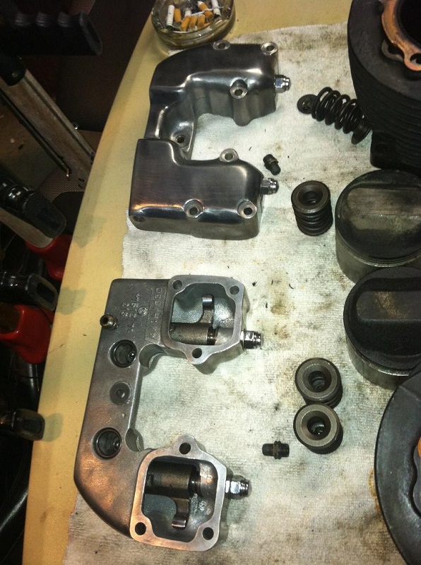
Rocker Box
Sub-Documents
* . . . Splitting Rocker Boxes
Interchangeability
Rocker covers are all the same technically from 1957 to 1985. 2)
Different part numbers are a different finish or style. There should be no concerns about mixing ones from different years respectively per side.
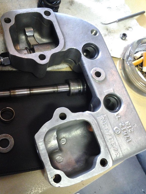
All rocker parts interchange in all boxes except end plugs (see below) and all boxes fit all heads. (1957-1985)
The rocker assm is one of the most trouble free areas on xls. Every rare once in a while you'll find a cracked shaft on late models. They make noise when cracked. All cracked were the late, no earlies.
However, rocker shaft end plugs must match the shaft because of it's thread pattern. 3)
- (1957-1970) Early shaft parts: Both the shaft and end plugs have 5/16”-24 threads. The shaft is 2 piece shaft & pressed on spool (15/16“ od). This is one of those little known facts. The end plugs have a single screwdriver slot.
- (1971) Change year shaft parts: the change happened during the 71 run. All 71's had the 1000 type boxes but came with both shaft/plug combos, depending on early or late model. This change was full on amf. Two pc shaft is way more expensive than one pc to manufacture and allen hex plugs removed the possibility of slipping with a power driver and damaging the cap at the factory. So assm person didn't have to be as “good”. Can't sell new bikes if they are scratched.
- (1972-1985) Late shaft parts: Both the shaft and end plugs have 1/2”-20 threads and the shaft is one piece. The end plugs have an allen key recess.
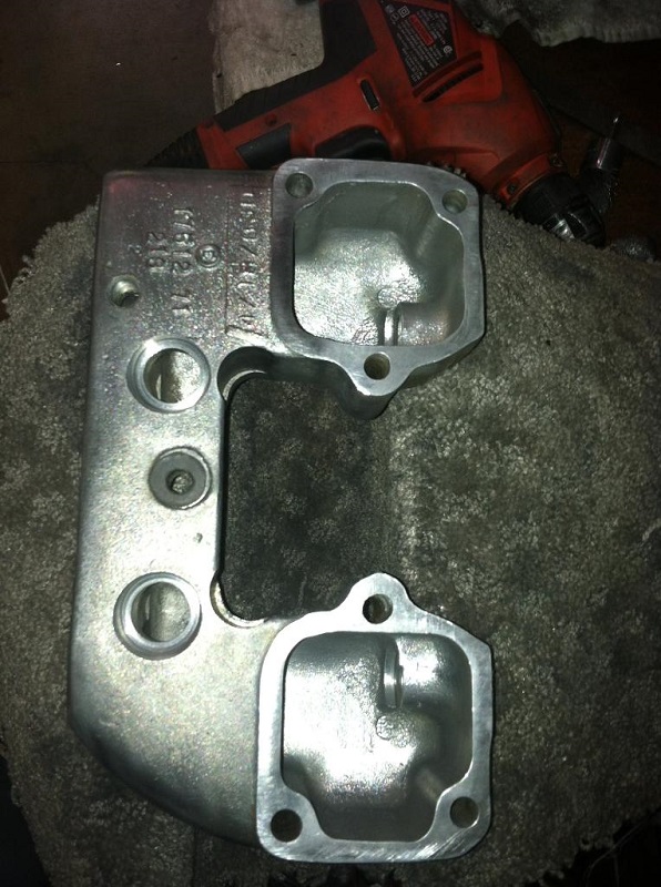
The boxes are also directional (having a front and a rear box respectively). It has to do with the location of the oil feed lines. 4)
The front box has the hole to the rear. The rear box has the hole to the front.
 |
|---|

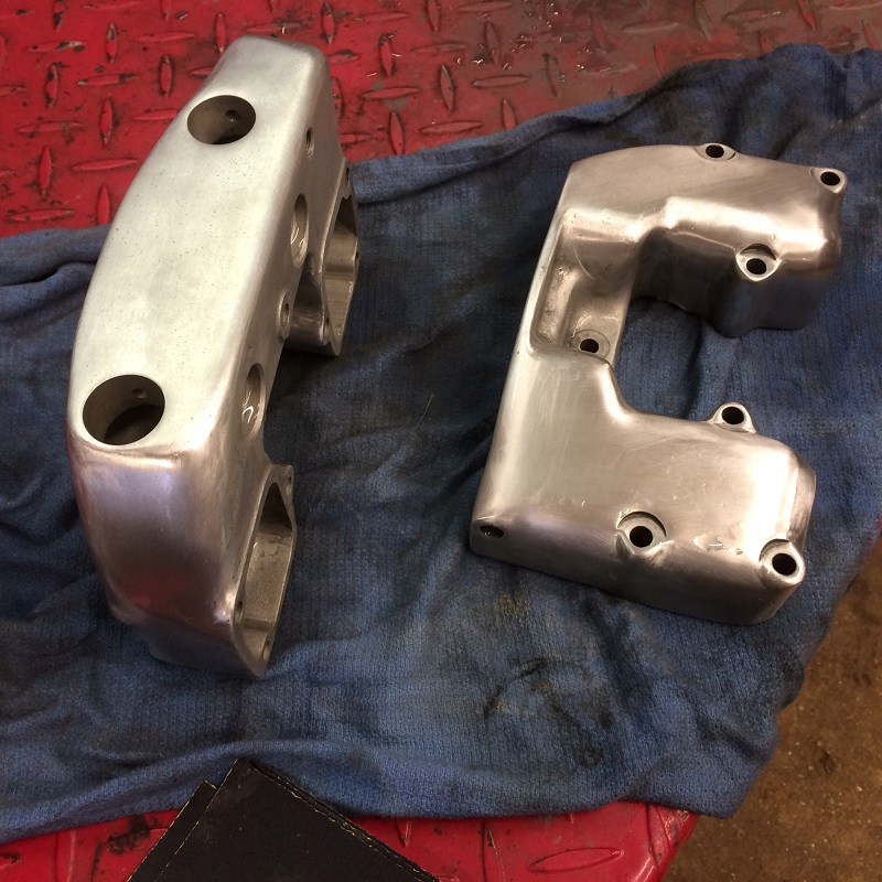
1957-1970
| Rocker boxes from a 68 XLCH. 10) | ||
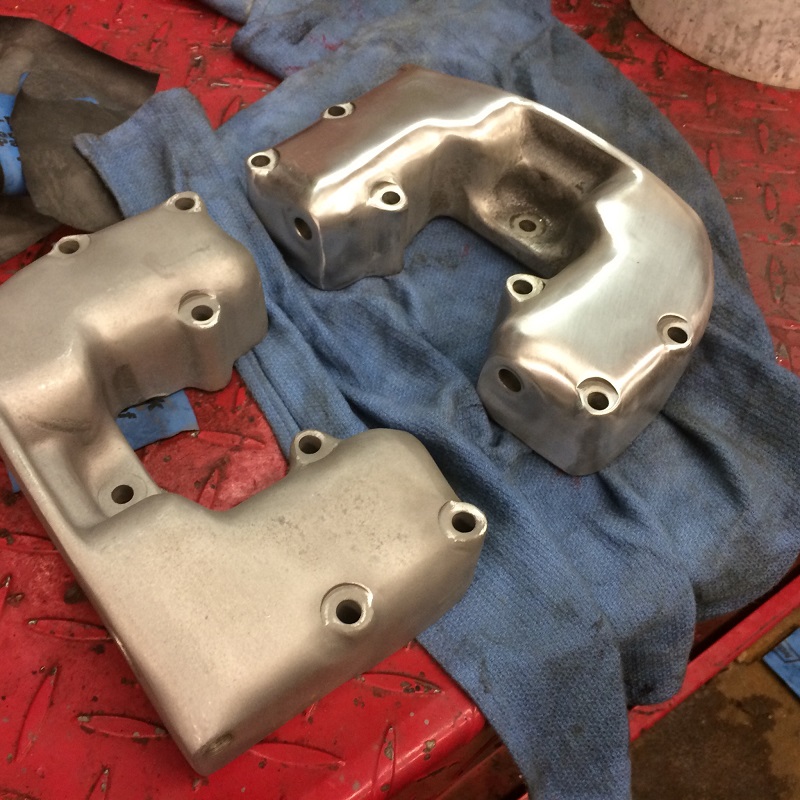 |  | 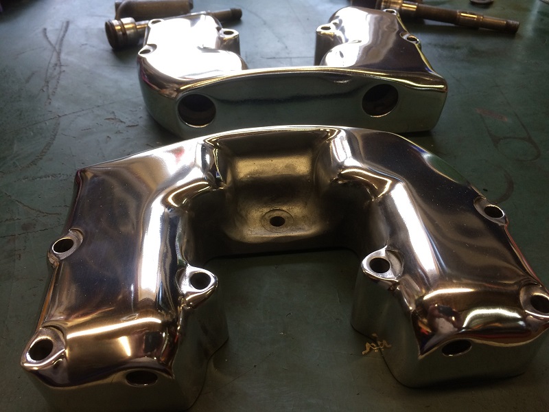 |
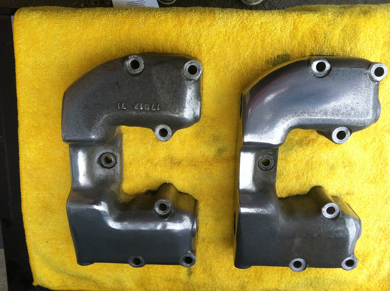
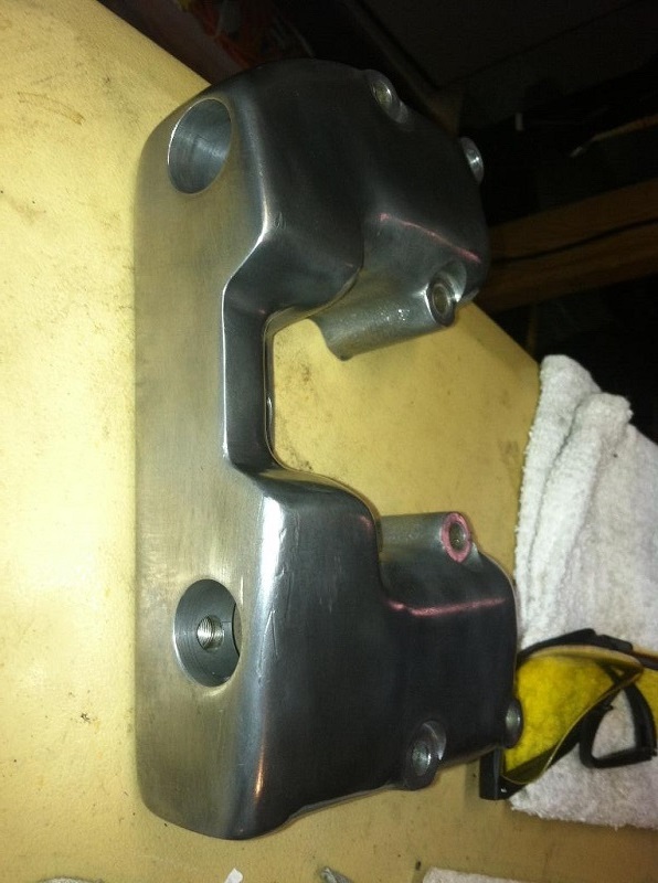
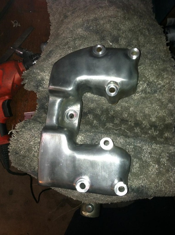
1971-1985 (except XLX)
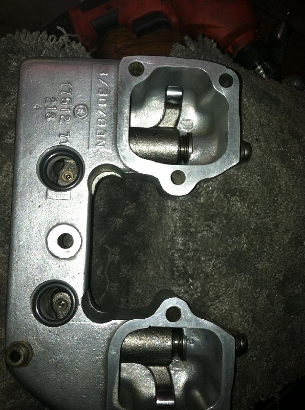
The 71 up have a thicker rib across the pushrod side and most people feel they're more rigid. 11)
They do look better under a strobe light than the early ones.
 12)
12)
| 71-85 rocker boxes (F: 17514-71 and R: 17515-71). 13) | ||
 |  |  |
 |  |  |
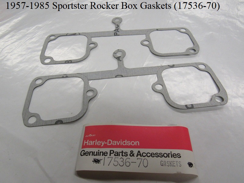
Rocker Box Gaskets
1957-1969 Sportsters did not come factory with rocker box gaskets.
Instead, a layer of silver paint was applied between each rocker box and head for sealing.
In 1970, a gasket (17536-70) was introduced and retros back to 1957 models. The same gasket is used on each rocker box (2 required).
Rocker Arms
| Rocker arms on a 69 XLH 15) | |
 |  |
Pushrod Tubes
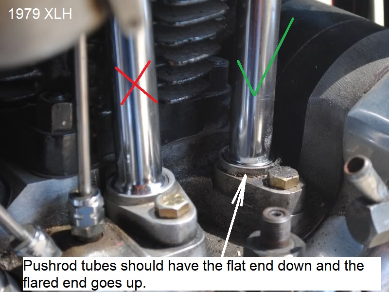
Pushrod Tube Orientation
The 1959-1969 Service manual has an (errored) illustration of the pushrod tube assembly.
The illustration shows the bottom tube upside down with the flared end facing the tappet block.
This is incorrect and has been corrected in the 1970-1978 as well as the 1979-1985 service manuals.
The flat end goes down and the flared end goes up.
And here is why. (Pushrod tube orientation by Dr Dick) 16)
Pushrod tubes seal in 3 places. 2 of those, the upper and lower corks, seal on their flat faces.
Now think about the center cork. What does it seal?
The only joint at center position is the telescope joint. So seal needs to be on outside of the upper tube where it meets the inside of the lower tube.
With the center cork being spring loaded into the flare on the lower tube;
The cork gets squeezed into the flare and 'chinese handcuffs' to the outside of the upper.
Not only does this seal the telescope, it tends to reduce the OD of the center cork as it squeezes around the inner tube.
So what?
Well, if you flip the lower tube so the flat is at center cork, the spring still squeezes the cork.
As the cork gets pushed thinner, it gets smaller on it's ID sealing just as it needs to.
But it also gets bigger on it's OD (sealing to the inside of the spring cup piece.
And trapping rain/wash water inside the cup above the cork (rusting the spring until it snaps).
Meanwhile at the bottom, the cork is getting squeezed into the flare.
Nothing is there for the cork to seal to until the cork gets small enough in diameter.
And fat enough in thickness that the tappet starts to be the thing it wants to seal to.
On a bike with stock or even .436 lift cams, this just creates a leak at bottom cork after enough miles.
But if you happen to have a bike with more lift– say .475 for instance, then the top of tappet may go above the cork seat surface of guide at full lift.
Now that extra tappet-cork kissing contest works the cork into the tube flare real fast.
Maybe fast enough that it constricts oil flow before you get home and notice the leak.
And the ensuing tappet/guide wear from letting the lube escape from the tube each time the tappets hits the cork.
(lifting it off the guide and letting lube out to the wind)
Look at the shape of the rocker box seat. Its reverse flare to squeeze the cork tight to the OD of the bore in the box.
So it don't fall down every time you open the tube.
You late model guys who have the full O-ring setup instead of corks, some of you may suffer from crappy top and bottom O-ring life.
When you take the bad O-rings out, they are smashed flat. To get rid of that, try putting corks in the center position only.
It's the center O-ring getting tighter an tighter that kills the end of the O-ring by not letting the tube to telescope shorter during hot cold cycle.
That's why the center O-rings are always jammed.
Periodic maintenance is one of the hallmarks of a devoted owner.
When possible, while building your ride working to extend the period between these required attentions may keep money in your pocket and your bike on the road.