Table of Contents
IH: Electrical System - Sub-03T
Pics and Information on Factory 1965-1985 Ironhead Horns
Horn Manufacturer
These are GM Delco-Remy automotive horns that were installed on Ironhead Sportsters. Harley Davidson did not make horns.
Per the Delco-Remy history website, Delco-Remy got into the horn business in 1924 with the purchase of the Klaxon Horn Company in Newark, NJ. 1) It had been determined that Remy could build the horn at a lower cost than Klaxon and the manufacturing equipment was moved from New York to the third floor of Plant One, where horn manufacture remained until 1946 when it moved to Plant 7. The manufacture of horns remained there until it moved to Plant 10 in the 1980's. This was its last location until the product line was sold in the late 1990's.
The Klaxon Horn.
A Klaxon type horn uses a motor-driven toothed wheel which ratchets against a metal stud attached to a diaphragm. Later horns would remove the motor and have the diaphragm activated by magnetic field from a coil of magnet wire.
The Sea Shell Horn.
The sea shell type horn replaced the Klaxon design. Even after the Klaxon design was replaced the term “Klaxon” was still used to mean an automotive horn.
The Snail Horn.
These were used on autos as well as 1965-up HD motorcycles. Just as before, the snail horn was also labeled as a sea shell horn or Klaxon horn. The snail horn has a distinct design of a snail shell due to the die-cast body revealing the air projection route from the diaphragm to the mouth of the horn outlet. In 1918, Delco Remy was purchased by and began operating as a division of General Motors and remained that way until 1994. 2) GM also sold these horns as “Klaxon Horns” whether the snail horn or the later flat backplate edition. As seen on early instruction sheets from Harley Davidson, HD sold or at least referred to the these as snail horns.
Numbers Found on Various Horns
The short of the story is it is not that easy to date these horns.
Per Delco Remy history page 3), Serial Numbers and Date Codes found on Delco-Remy parts: Originally the parts were given a serial number in numerical order. These numbers are usually on the older part numbers that were three to four numbers and a letter. Later when DR went to seven digit numerical only part numbers, an actual date code was instituted on oval DR ID tags. The first number is the year, followed by a letter representing the month, and the last number was the day of the month. The numbers were originally stamped on but later rolled for cost reduction.
A date code of: 3B22 would have been built in the third year of the decade (this has to be figured from the year vehicle it came on), and February 22nd. Below are the monthly codes which did not use “i” as it looks like a 1. Jan - A, Feb- B, Mar - C, Apr - D, May -E, Jun -F, Jul - G, Aug - H, Sep - J, Oct - K, Nov - L, Dec - M.
On further research 4), there have been horns known to have the month and year in reverse based on owner vehicle data researched.
It also seems there are conflicting stories whether the last number of the date code denotes the day or the week on DR horns,
(against the grain from generator, regulator etc. type date codes).
Example: A horn with 7G3 (1967, July, 3rd Week) date code may end up as 3G7 instead from a factory install.
And on early horns, the date code may be readably stamped or the last number would fall off the ID pad.
As normal for the time, it seems quality control was an issue in the stamping department.
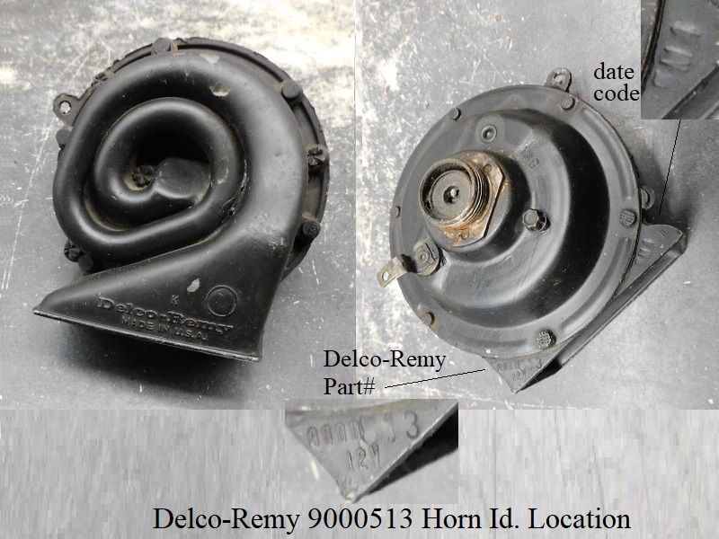
Numbers found on the horn itself;
- Die-cast horns:
- The die-cast horns have a (Delco Remy) 7 digit part number stamped on the bottom left corner when facing the back (mounting side of the horn.
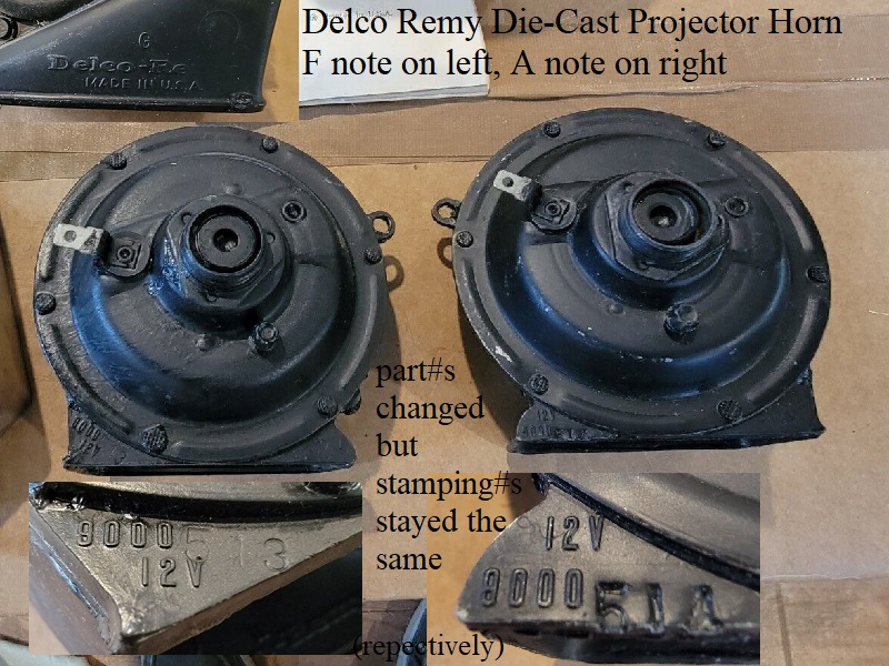
Within the 7 digit part number, the first 4 digits are the horn series (9000) and the last 3 digits pertain to the horn tone.
Is it a coincidence the Harley part numbers for standard “F” horns begin with 6(9000)-..?
F tone (low) horns last 3 digits are (513) and A tone (high) horns last 3 digits are (514). - The date code is stamped on the bottom right opposite the part number.
In the case of twin horns found on a Sportster (as in the factory kits), it'd be extremely uncommon to find matching date codes on the two horns. - Early die casts were stamped on the projector side bottom right and coded for the signal tone it produced above the molded “Delco Remy” signature.
Example: (LO) for low tone, (HI) for high tone etc). - Later die-cast horns had one letter embedded inside a circle in the same location.
Example: Circled (L) for low tone, circled (H) for high tone. - There are also, unknown at this time, other small letters in various places.
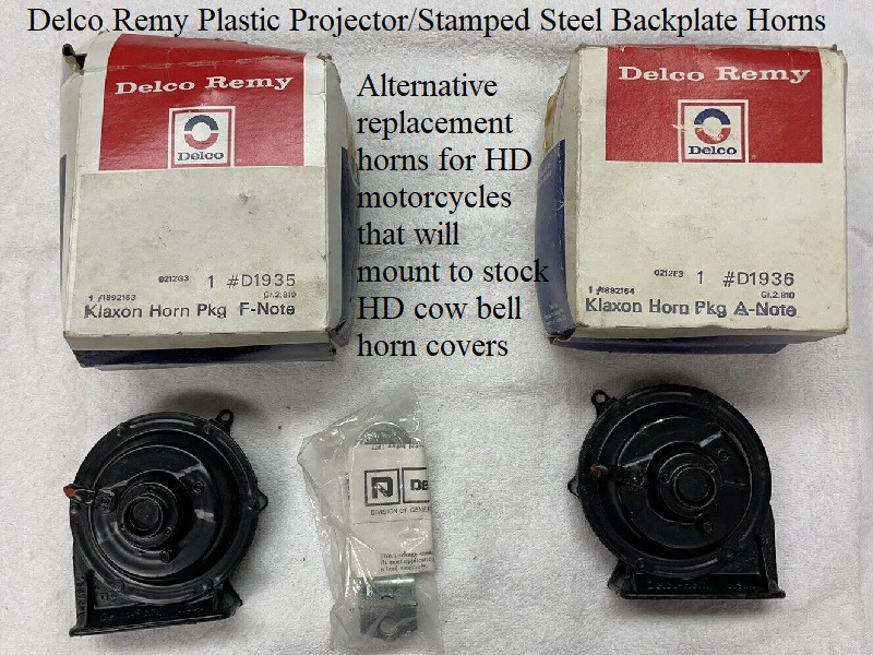
- Plastic/Steel horns:
- The plastic horns do not have the part numbers on them. “Delco Remy” is molded on the rear of the projector's outlet.
- The horn tone is denoted by the actual letter stamped of the musical note it produces molded on the long side of the rear projector outlet.
Example: (F) for low tone or (A) for high tone etc. - Instead of the part number, there is a 6 digit serial number near the tone letter past a molded divider.
The first 3 numbers pertain to the signal tone. The last 3 are either a date code or sequential number.
Noted below are date codes / serial numbers found on some plastic/steel horns and comments based on the above information.
All horns noted have screw/nut mounting with removable brackets. - F Horns:
- 1305E3, 1306F2, 1307H5…. number combinations all begin with 130. Last three seemingly (Year, Month, Day) except for a 130D1L.
- 130422, 130521, 130704…. number combinations all begin with 130. Last three seemingly all sequential numbers.
- A Horns:
- 1317L3…. number combinations all begin with 131. Last three seemingly (Year, Month, Day).
- 131542, 131640, 131951…. number combinations all begin with 131. Last three seemingly all sequential numbers.
- C Horns:
- 1416C2… number combinations all begin with 141. Last three seemingly (Year, Month, Day)
- European standards:
- If you find an “E” inside a circle or box on the horn, this is the European standard code number. The part is “E” approved.
The uppercase “E” in a circle means the device is type approved to an ECE Regulation.
While the lowercase “e” in a box indicates the device is type approved to an EEC Directive.
It's rare to find one marking without the other, since the requirements are essentially identical. 5)
The number after the “E” or “e” signifies the country in which approval was granted.
The coding “Circled, E-6” has been found on NOS HD factory replacement horns which adheres to Belgium standards.
A large portion of auto horns have spot welded mounting brackets and will not easily mount to a Harley without modifications.
And there were horns for autos that had brackets that mounted onto the nut on the back as did horns used on Harleys.
These type auto horns are basically the same as the ones HD used with the exception of a vast array of bracketry depending on make/model.
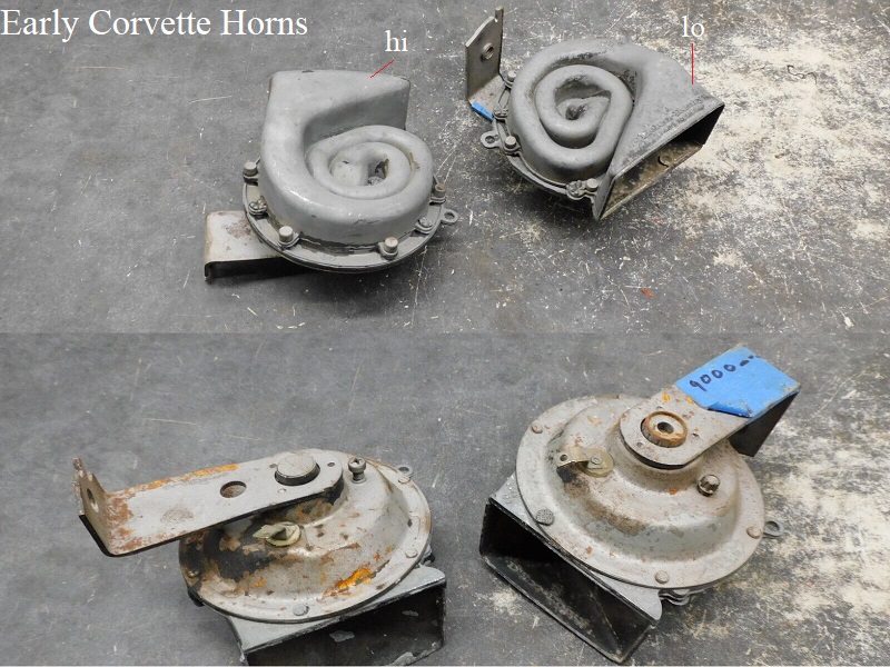
| Delco Remy twin horns (Lo and High) from early Corvettes with spot welded brackets 6) | Delco Remy Die-Cast Low (F) Horn with removable bracket 7) | NOS Delco Remy Die-Cast Horns with removable brackets 8) |
 |  |  |
| NOS Delco Remy D1935 F note and D1936 A note horns with the nut/screw on rear for brackets 9) | |
 | 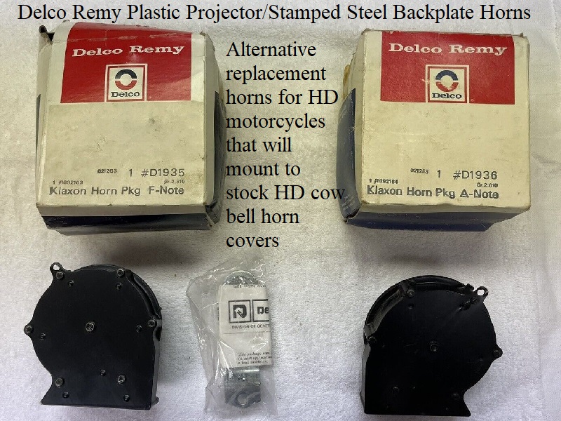 |
Horn Cross References
1965-1985 Sportsters used Delco-Remy 12V (snail or seashell) horns.
There were about 5 different tones produced by Delco Remy according to their “history” page. 10)
Sportsters only used the F and A tones.
The main differences between these horns are the mounting brackets and horn tone.
Lo-Tone is an “F Note”, Hi-Tone is an “A Note”, Deep-Tone is a “D Note”, Penetone is a “High C Note” and the Alarm Tone is a “High F Note”.
It's also important to note that there was a Hi-Tone “F Note” only used on Corvettes.
The horn part#s in the chart below all have the screw/nut bracket configuration as is seen on Harley horns of the period.
There are HD part#s if known along with Delco-Remy and General Motors part#s.
The horns listed interchange. The (separate) brackets that might come with them will not interchange with Harley Davidson motorcycles.
But if you are searching for a period correct horn, any of these will work as listed below. Just toss the included bracket since it's not welded on.
The 9000XXX numbers are the horn part# itself and the superseded numbers are horn and bracket assemblies.
 |
|||||
|---|---|---|---|---|---|
| Harley Davidson / Delco-Remy Die-Cast Horn Cross Reference | |||||
| HD Part# | Horn Tone | Delco-Remy Part# | Superseded by 11) | Superseded by | Superseded by |
| 69000-65 | F | 9000513 | 9000239 | D1926 | D1935 |
| 69001-70 | H | 9000514 | 9000011 | D1932 | D1936 |
| Harley Davidson / Delco-Remy Plastic/Steel Horn Cross Reference | |||||
| HD Part# | Horn Tone | Delco-Remy Part# | GM Part# 12) | ||
| 69000-76 | F | D1935 | 1892163 | ||
| 69016-76 | A | D1936 | 1892164 | ||
| ? | C | D1939 | 1892246 1892247 | ||
| ? | D | D1934 | 1892162 | ||
Standard Sportster Horns (low note)
Delco-Remy (LO-tone, or F note) 9000 series horns (9000513) were factory installed on production Sportster models from 1965-1985.
The standard horns used on HDs all have their cover mounting “ear” facing the left, or toward the front of the bike, when mounted.
These are also known as “cowbell” horns on HD motorcycles as the horn cover drops down between the cylinders reminiscent of a cow bell.
These same horns were also installed on FX and other HD models as well as GM autos of the time.
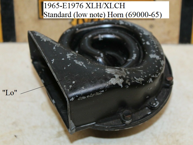
1965-E1976
1965-E1976 HD horns were 12v and made of die cast aluminum, HD (69000-65).
| 1965-E1976 Standard Low Note Horn (69000-65) 13) | |
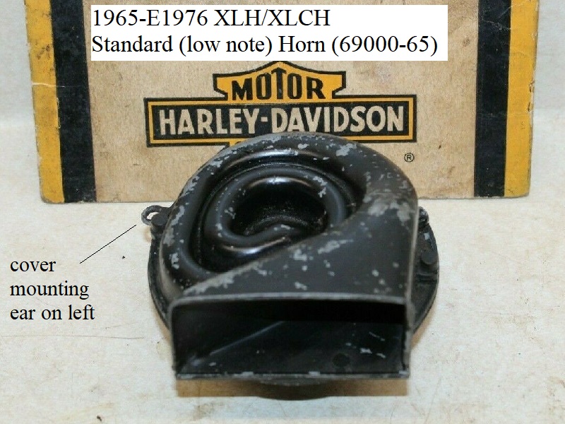 | 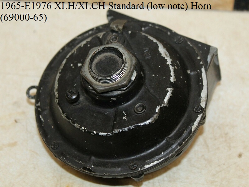 |
| 1965-E1976 Standard Low Note Horn (69000-65) 14) | |
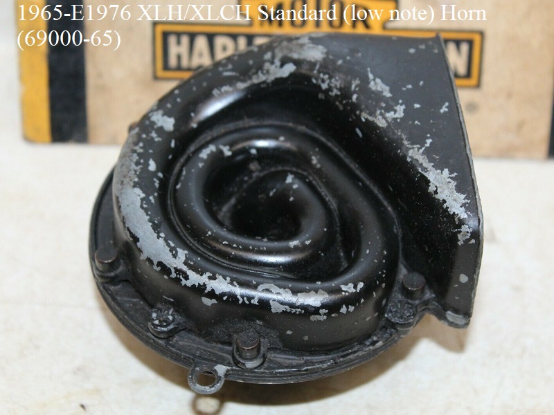 |  |
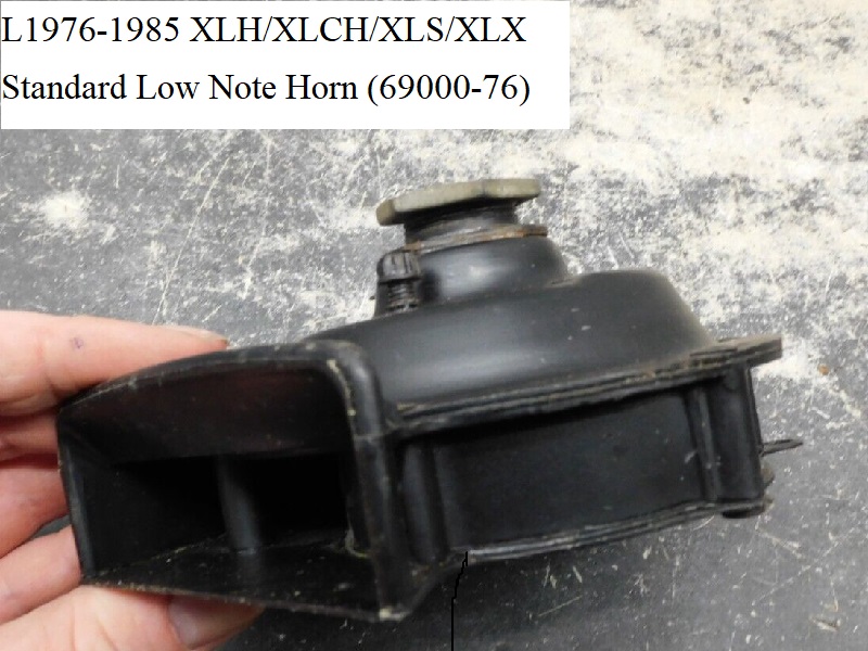
L1976-1985
L1976-1985 HD horns were 12v and made of plastic rear projectors with the back shell and back plate made from stamped steel, HD (69000-76).
The steel plates hide the air path labyrinth as seen on 65-E76 horns.
The L76 horn was also parts order replacement for 1965-E1976 XLH and XLCH.
| L976-1985 Standard Low Note Horn (69000-76) 15) | |
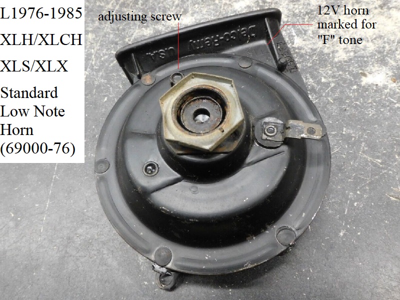 | 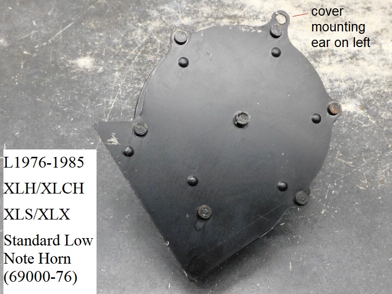 |
| L1976-1985 Standard Low Note Horn (69000-76) 16) | |
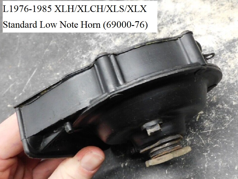 |  |
High Note Horn Option for Sportsters
High note (A) horns were available individually as optional replacement parts on Sportsters from 1970-1978.
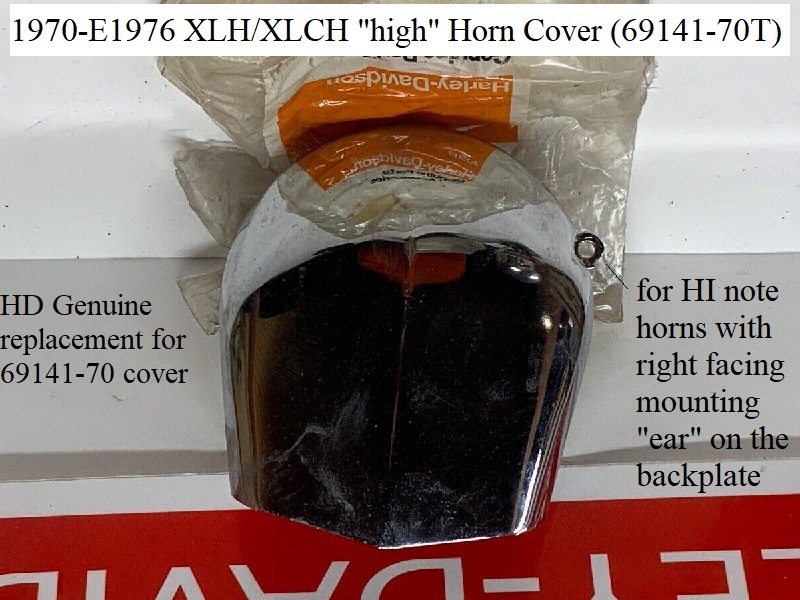
However, due to the mounting ear location change, the high note horn cover must be used.
The cover mounting ear is noticeably facing the right, or toward the rear of the bike, when mounted.
These same horns were also installed on FX and other HD models as well as GM autos of the time.
The high note horns were also available in the “twin horn” kits. From 1979-1985, they were only available as part of the twin horn kit.
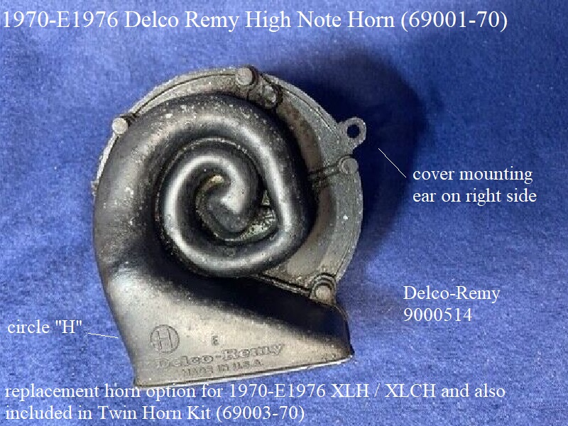
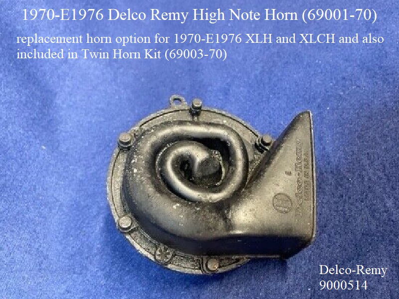
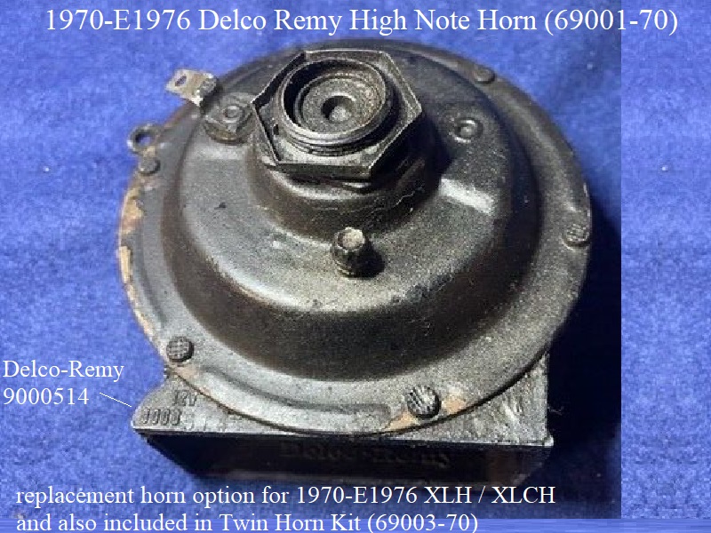
1970-E1976
1970-E1976 Sportster Horn (69001-70) is die-cast aluminum and is basically a mirror image of it's low note horn counterpart.
From 1970-E1976, it could also be ordered as part of Sportster Twin Horn kit (69003-70). The same horn was also included in FL/FX twin horn kits.
| 1970-E1976 High Note Horn (69001-70) 17) | ||
 |  |  |
L1976-1985
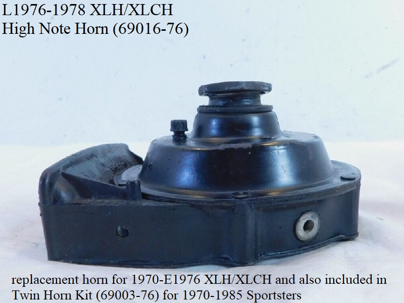
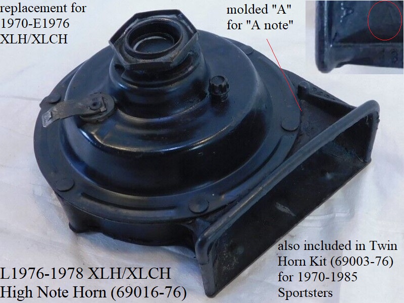
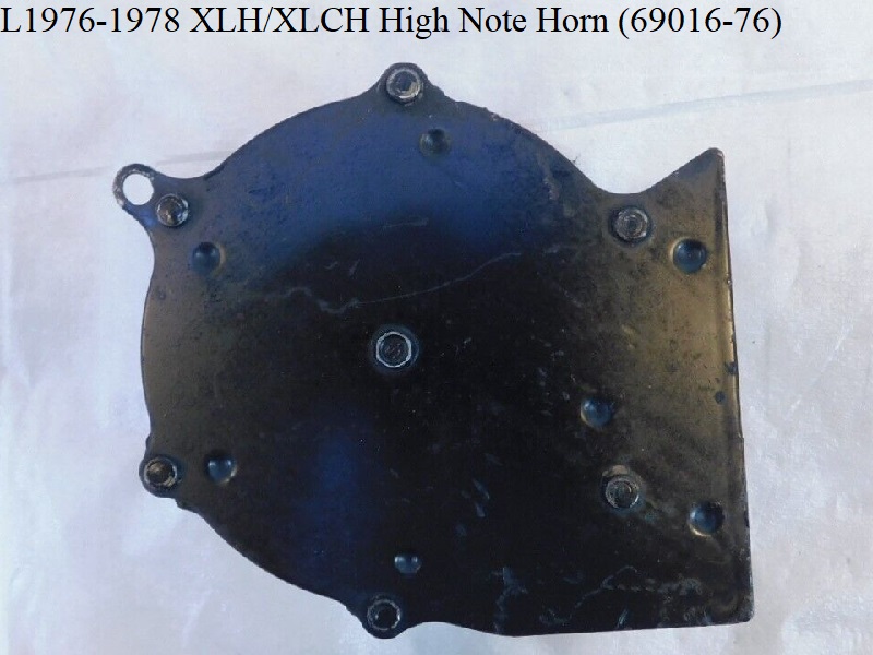
L1976-1978 Delco Remy (69016-76) has a plastic rear projector and stamped steel backplate is a mirror image of it's low note horn counterpart.
It was optional parts order replacement for 1970-E1976 XLH and XLCH. The MoCo stopped selling this horn as an optional individual replacement part in 1979.
From 1979-1985, it could be ordered as part of Sportster Twin Horn kit (69003-76). The same horn was also included in FL/FX twin horn kits.
| L1976-1978 High Note Horn (69016-76) 18) | ||
 |  |  |
Horn Cover
Just as the same horns are used on Sportsters as well other BT models, so is the same horn cover.
So those labeled below also fit their respective horns on other HD models too.
The Hi and Lo horns are mirror images of each other with each having the mounting “ear” on the opposite side of the other.
So as with the other mounting screws.
When looking for new or used covers, be sure to keep mounting requirements in mind for the horn you'll be using.
1965-E1976 HD
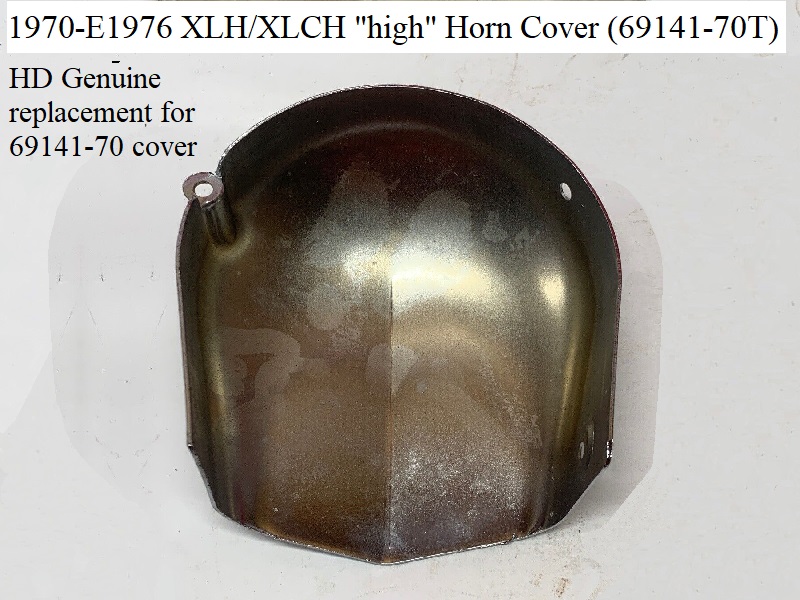
| 1970-E1976 XLH-XLCH “high tone” Horn Cover 69141-70T 19) | |
 |  |
L1976-1985 HD
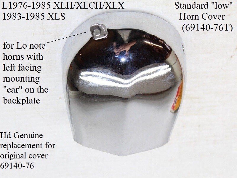
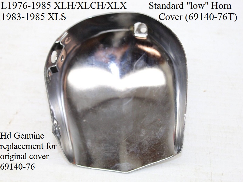
| L976-1985 Sportster Standard “low tone” Horn Cover (69140-76T) 20) | |
 |  |
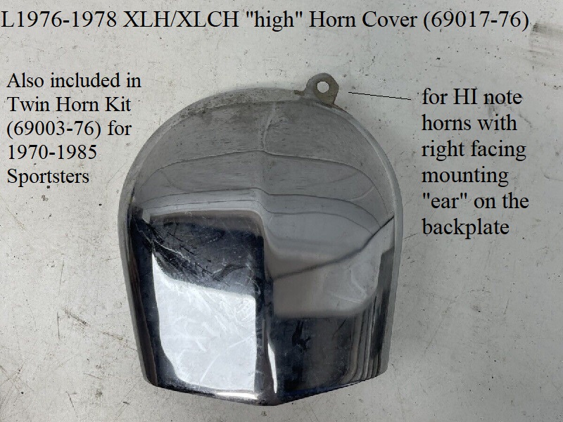
| L1976-1978 XLH/XLCH “high tone” Horn Cover (69017-76) 21) | |
 | 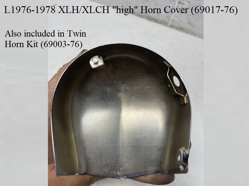 |
Twin Horn Kits
The twin horn kits mistakably make one think there are two horns in the package.
Maybe it would have been more understandable it was marketed as an additional horn and parts for creating a dual horn system.
The twin kits only have 1 high note horn in them to add to, or accompany, your stock low note horn creating twin horns.
Also, the low and high horn bodies are mirror images of each other and (constructed opposite).
So the cover for the low horn will not fit on the high horn and vice-versa.
The kits also include bracketry, wiring and fixins to attach and plug both horns into the system.
Twin horn kit (69003-70) was sold for 1970-E1976 XLH and XLCH.
This kit appears in the 1971 parts and accessories catalog as (twin horn kit).
The 1972 P&A catalog lists the kit contents as 1 horn, 2 chrome horn covers, all wiring and fittings.
It has added verbiage “The horn already on the vehicle is used in combination with the one in the kit”.
“Each has a different tone which blends into a pleasing and powerful blast”.
Twin horn kit (69003-76) was sold for L1976-1985 XL, XLCH, XLS and XLX models.
By 1978, 69003-76 kit had replaced -70 kit for 1970-up models.
Below are the contents of this kit from the 1979 Sportster parts catalog.
| |
||
|---|---|---|
| 69003-76 Twin Horn Kit Consists Of 22) | ||
| 1719W SCREW | No. 8-32 x 5/8 Phillips hd. (6) | 3206B SET SCREW, No. 8-32 x 3/16 socket hd. (2) |
| 7015 LOCKWASHER, No. 8 (4) | 7041 LOCKWASHER, 5/16 (4) | 7608 NUT, No. 8-32 x 1/8 x 11/32 hex. (4) |
| 7748W NUT, 5/16-18 x 17/64 x 1/2 hex. (4) | 10006 CABLE STRAP (5) | 10026 CLAMP, twin horn (2) |
| 69016-76 HORN, high note | 69017-76 COVER, high note horn | 69117-65 MOUNTING BRACKET, only (2) |
| 69125-65 RUBBER MOUNT, 5/16-18 threads (2) | 69140-76 COVER, low note horn | 69144-65 SPACER, horn cover |
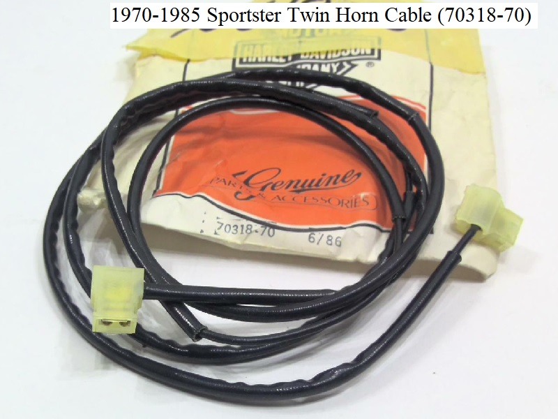
| 69149-65 MOUNTING NUT, horn | 70016-65A HORN GROUND STRAP (braided) (2) | 70318-70 CABLE ASSEMBLY, twin horn |
| 70576-68 WIRE CONNECTOR | 70584-69 INSULATOR, flag terminal (2) | |
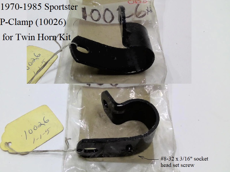
The P-clamp (10026) in the kit is the same type as used on FL/FX model twin horn kits but smaller in dia. (XL P-clamp reportedly 1“ dia).
According to the 1941-1984 FL parts catalog, it mounts to the frame (10025 CLAMP, horn to frame, l or 2).
It stands to reason it would mount around the front downtube with the set screw in the rear to pinch into the downtube holding the horn assembly in place.
Without the instructions in the kit, there isn't another pliable explanation for it's placement.
The length of the included wire supports that theory (rumor has it there were (2) wires in the kit).
There hasn't been any indication that an engine guard had to be installed to use the twin horn kit.
Bracketry and Hardware
The horn mounting brackets are not the actual motor mounts but rather attach to the motor mounts.
Click Here to view information on motor mounts.
There was a truck load of changes in the horn mounts between late 1970 till 1975. 25) The changes weren't really cataloged in the part books.
Basically:
1965-1970 all used the same geometry. 1965 and 1966 used different stuff than 67> but the end result was same.
And this 1st gen stuff was used on some 1971's, maybe even some 72's also. This set up used the larger diameter, short, stiff, 5/16” stud rubber mount.
It held the horn way more solid than the later smaller, longer, 1/4“ stud rubber mount. Both 1st gen brackets had less inward offset than any of the later ones.
The shananigans began in late 1970 with the intro of the 'low' seat kit.
1971 and maybe the 1972 bikes that came from the factory using the older standard seats supposedly came with the 1st gen 65-70 setup.
In late 1971, the low seat was available factory installed for the 1st time.
The low seat required the ignition switch to be moved from the right side under the high seat to the left side on top motor mount where it fouled the horn brackets.
At first, the new brackets with deeper offsets that opened up room for switch were supplied that used the old 5/16” rubber.
There were some issues with interference. The smaller rubber mount and another set of new brackets were furnished to solve that issue.
But the 1/4“ rubber mount let the horn flop around to much hitting fins and/or shaking the wire loose from the slip-on terminal.
The bumper was the fix for this. This 3rd gen setup was used till 1974. In 1975, a bigger ignition switch was used. New brackets again, 4th gen.
There are so many different brackets used that having mismatched stuff is common changing horn position to who knows where.
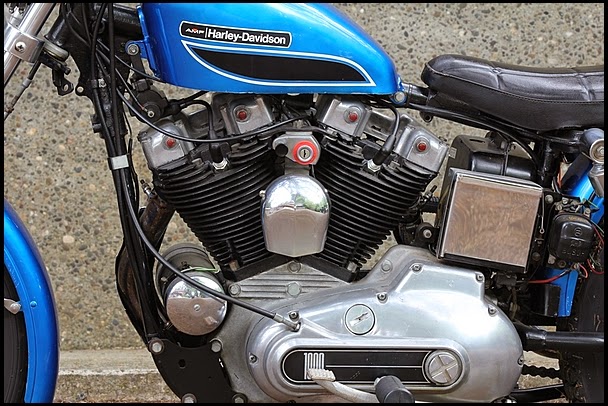
The pics below show the low seat key switch position and orientation for E1971 and 1972 Sportsters. 26)
The low seat required the switch to moved to the motor mount as mentioned above but it was a real tight fit between the horn bracketry and the rear head on E1971 models.
Take a close look at the early 1971 XLH below fitted with the “2nd version” of the accessory seat setup.
see that switch bracket?
Note the key switch alignment with the choke pull.
The factory 1972 XLCH below has the key switch higher by .09” and forward by .06“
There were new horn brackets in 1972 used with this that gave more, behind the switch, clearance.
The 72 switch housing itself is physically smaller (the red off-run-lights washer behind the switch was tossed by almost everyone owing a 72).
Horn Mounting Bracket
This is the bracket the horn directly mounts to. All 1965-1985 Sportster horns are basically hung from a bracket between the cylinders on/from the motor mount.
The horn is hard mounted to it's bracket by a nut on back of the horn with a rubber isolator mount between the horn bracket and it's supporting bracket.
Also note, these horns are designed to mount with the mouth of the projector pointing down to drain any condensation that may gather inside.
Mounting the horn in any other position requires a drain hole due South through the projector path from the position the horn is mounted.
1965 XLH/XLCH used horn bracket (69052-65).
1966 XLH/XLCH used horn bracket (69052-65A). This bracket was parts replacement for 1965 models.
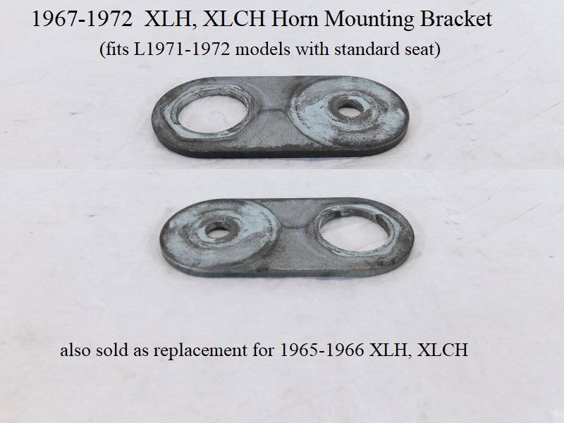
1967-1972 XLH/XLCH with the standard seat used horn bracket (69117-65). This bracket was also parts replacement for 1965-1966 models.
Two of the 69117-65 brackets were also included in Twin Horn Kit 69003-76.
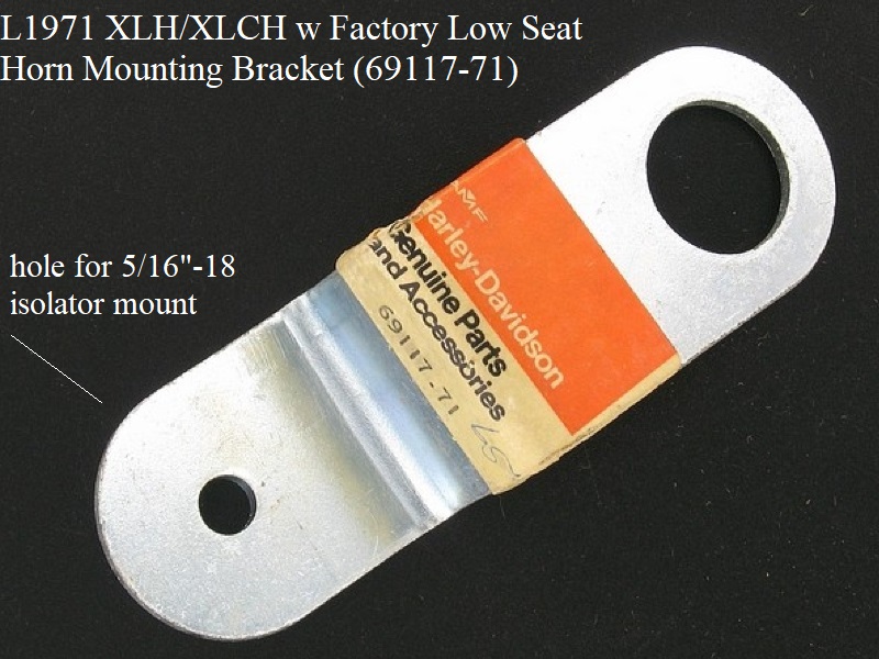
L1971 XLH/XLCH used horn bracket (69117-71).
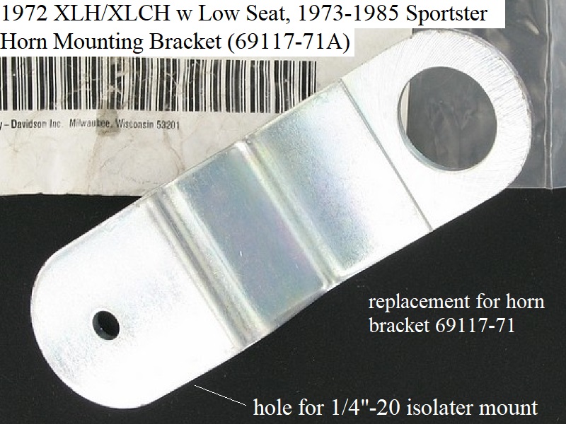
1972 XLH/XLCH w/ the low seat and 1973-1985 Sportsters used horn bracket (69117-71A), also parts replacement for L1971 models.
Click on any pic to enlarge:
Horn Support Bracket
The horn support bracket attaches to the motor mount and hangs the horn/bracket/cover.
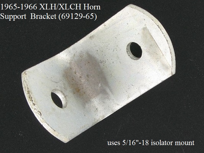
1965-1966 XLH/XLCH used horn support bracket (69129-65).
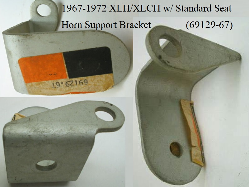
1967-1972 XLH/XLCH models that were fitted with the standard seat used horn support bracket (69129-67). This bracket also supports the choke cable.
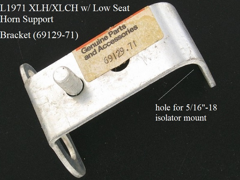
L1971 XLH/XLCH factory fitted with the low seat used support bracket (69129-71) which also supports the choke cable and the ignition switch.
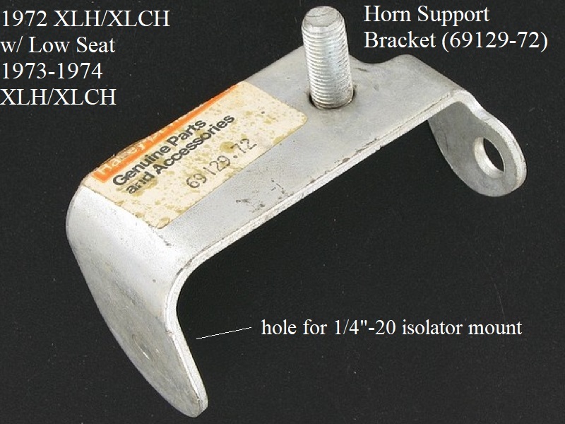
1972-1974 XLH/XLCH used support bracket (69129-72) and holds the choke cable and ignition switch.
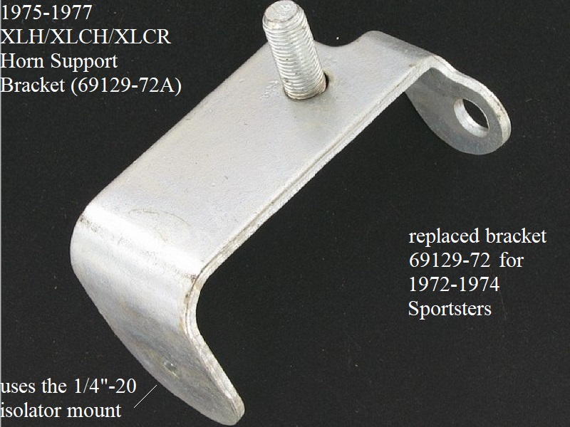
1975-1977 XLH/XLCH/XLCR used support bracket (69129-72A). This bracket was parts replacement for 1972-1974 models. Supports choke cable and ignition switch.
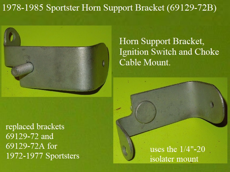
1978-1985 Sportsters used support bracket (69129-72B). This bracket was parts replacement for 1972-1977 models. Supports choke cable and ignition switch.
Click on any pic to enlarge:
Rubber Isolator Mount
The rubber mount isolator is a vibration damper for the horn between the 2 mounting bracket involved to mount it.
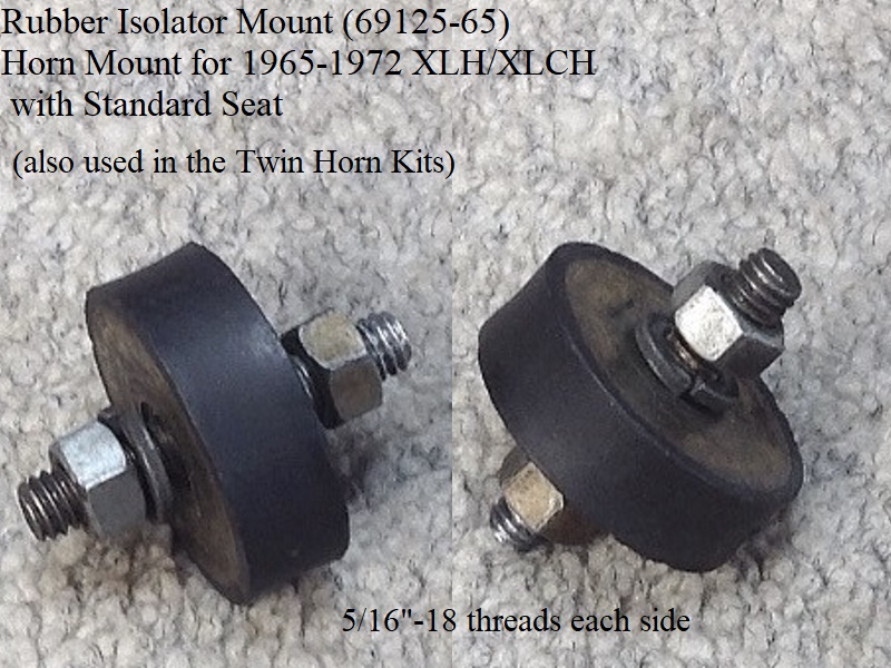
1965-E1970 rubber mount (69125-65) has 5/16”-18 threads each side.
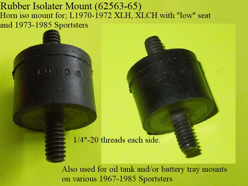
L1970-1985 rubber mount (62563-65) has 1/4“-20 threads each side.
In L1971, the low seat was available factory installed for the 1st time. 38)
The low seat required the ignition switch to moved from right side under the hi seat to the left side on top motor mount (where it fouled the horn brackets).
At first new brackets with deeper offsets (that used the old 5/16” rubber mounts) were installed that opened up room for the switch.
There were some issues with interference and the smaller 1/4“ rubber mount and another set of new brackets were furnished to solve that issue.
The 1/4” mount was also used on various 1965-2003 Sportster battery trays and oil tanks.
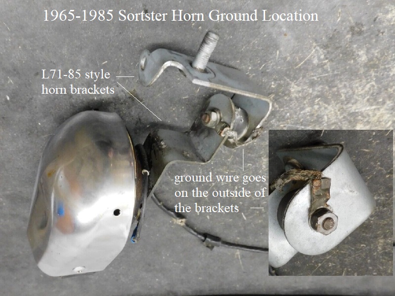
Grounding the Horn
The horn ground is the metal part of the body. The mounting bracket carries the ground to the rubber isolator mount where ground stops.
To continue ground, a strap is placed on each side of the isolator mount.
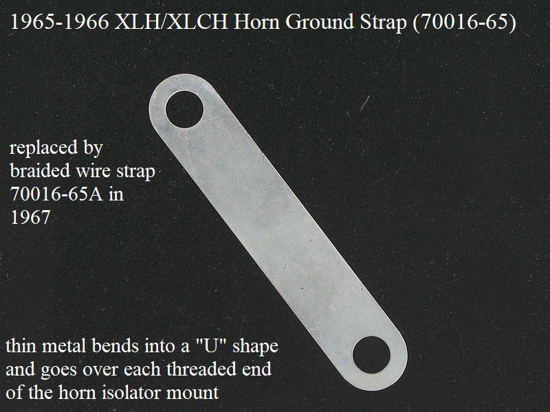
1965-1966 horns were originally grounded with a straight metal strap (70016-65) that was then bent in a “U” shape with holes on each end.
The holes slipped over the studs on each side of the rubber isolator mount and tightened along with the bracket assembly.
This metal strap was replaced by the 1967 braided strap.
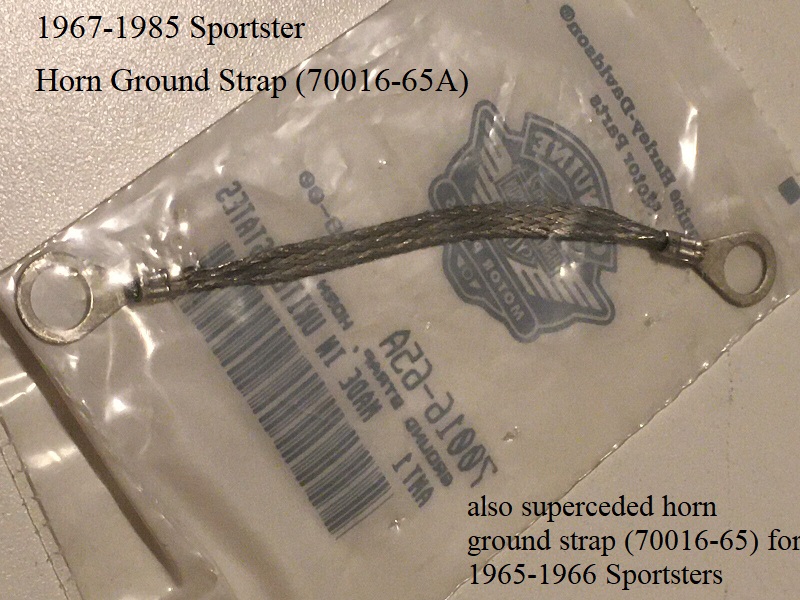
1967-1985 models replaced the metal strap with a short braided wire with ring terminals on each end (70016-65A).
The ring terminals slip over the studs on each end of the isolator mount and tightened along with the bracket assembly.
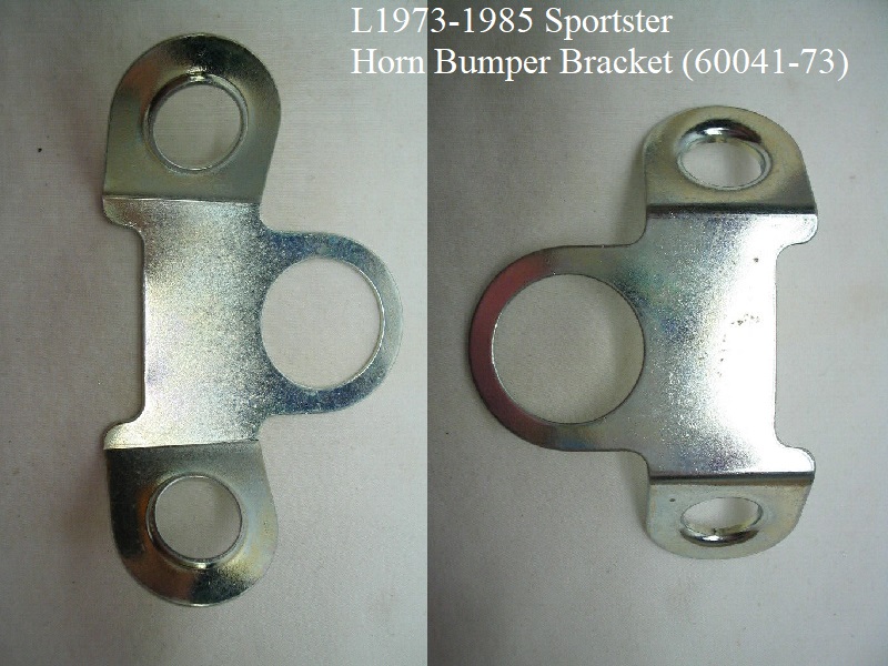
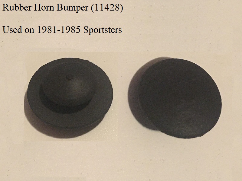
Horn Bumper Bracket (L73-85)
The bumper bracket came about in late 1973 due to a rattling horn problem on L71-E73 “low seat” bikes. 44)
The bracket part number is (69041-73) and it has the large hole in the center to go over the horn threads on the horn mount bracket.
Also there are 2 smaller holes on each end to pop rubber bumpers (69042-73) in to damper horn movement.
The rubbers keep the horn from flopping around too much, hitting fins and/or shaking the wire loose from slip-on terminal. 45)
The bumpers got a new part number in 1981 to (11428).
Hardware
V-Twin Mfg. has a Horn Cover Mounting Hardware Kit (37-8804) that includes the 3 screws, 3 lock washers, 3 hex nuts, 1 speed nut and 1 spacer.
Their add says these parts replace HD 1719W, 7015, 7608 and 8125.
| 1965-1985 Sportster Horn Cover Spacer (69144-65) 48) |
