Table of Contents

EVO: Oiling & Lubrication - Sub-04G
Pics and Information on 2004-2009 Sportster Oil Tanks
See also in the Sportsterpedia;
….. *1986-Up Oil Line Routing
….. *Pics and Information on stock EVO Battery Trays and Parts
Note: These tanks are prone to leaking and / or bursting.
Click Here for more in formation on 2004-Up Oil Tank Leak Issues.
In 2004, the MoCo started using plastic oil tanks.
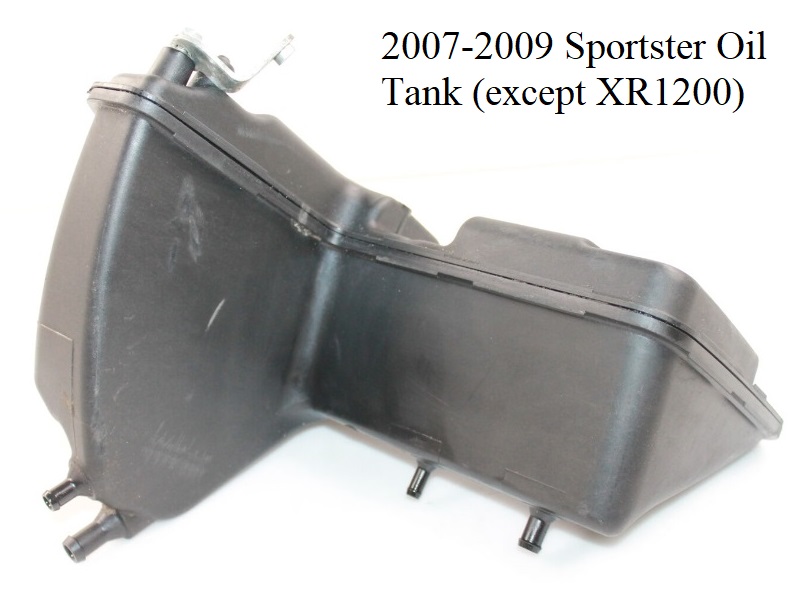
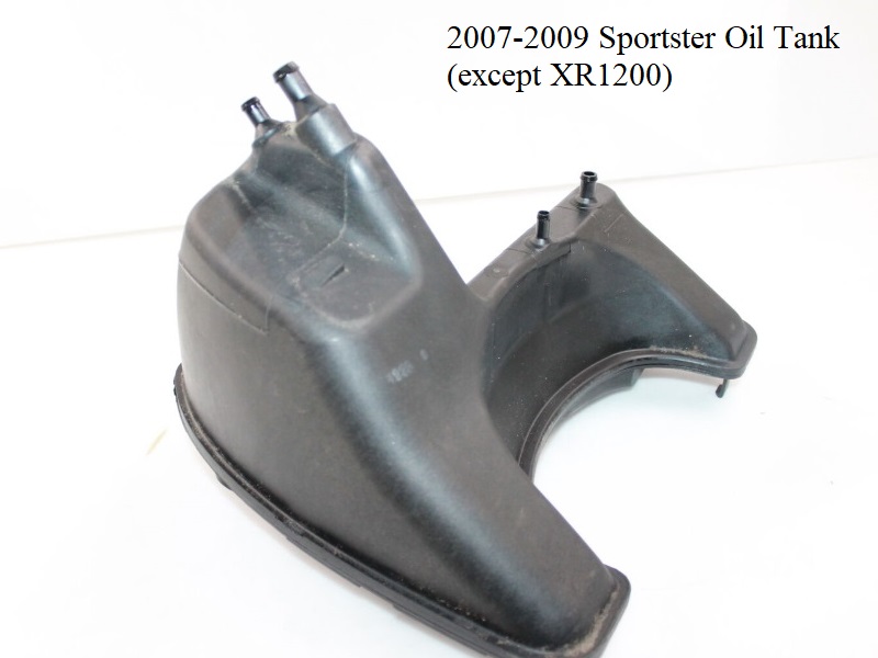
There were two factory installed versions, 04-06 (62888-04) and 07-09 (62888-04A) for all models except XR1200/XR1200X.
XR1200 and XR1200X models use tank 2007-2009 tank (62888-08) and 2010-2013 tank (62888-08A).
The 04-09 oil tank versions share the same basic setups as the oil tank and electrical junction box (that is vulnerable to moisture). 1)
The EFI bikes use up more space in the junction box, having an additional relay and more fuses?).
The 07-09 tank has a less restrictive cavity in the top section than the 04-09 tank to allow more free flowing air back to the cam chest.
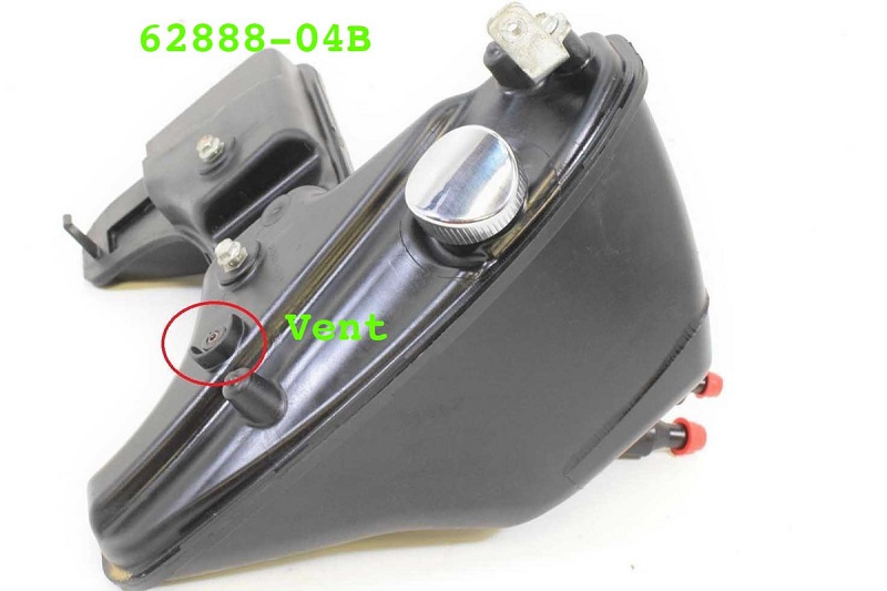
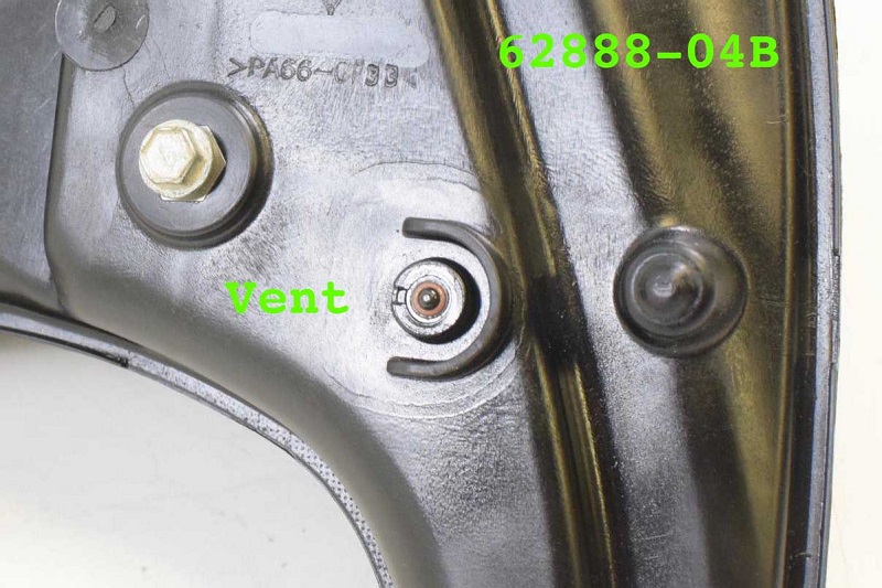
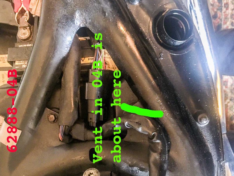
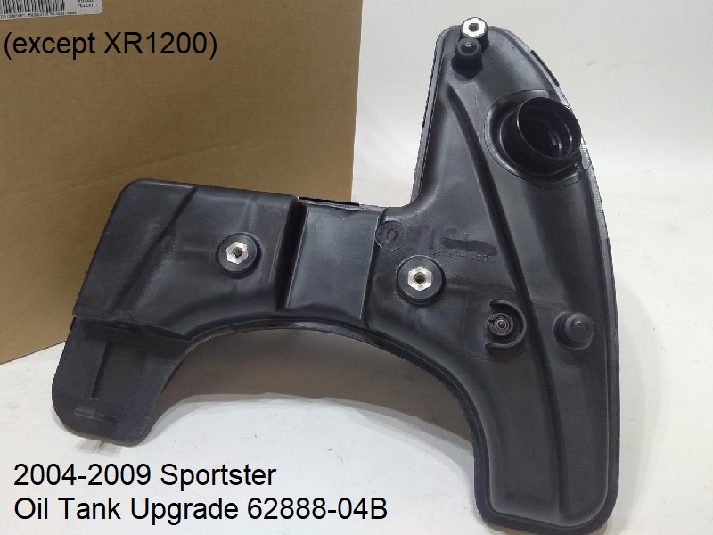
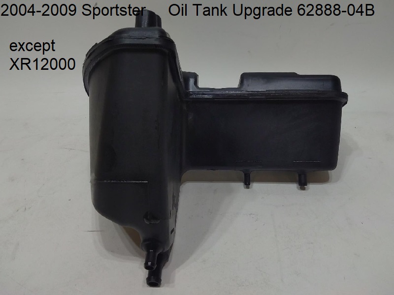
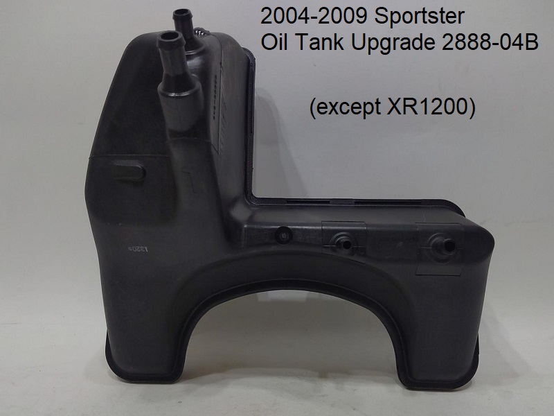
Late 2009, they came out with an upgrade version (62888-04B) with a 10 PSI pressure relief valve in the top of the tank, right side.
The -04B tank fits 2004-2009 Sportsters and also has a less restrictive vent tube configuration inside the tank.
However, the -04B has now been obsoleted as well..
The 2010-2013 oil tank (62954-10) will fit 2004-2009 models (except XR1200/XR1200X) and it also has the 10psi relief valve. 2).
The hose fitting locations changed again so you'll have to reroute the hoses to use this tank on 2004-2009 models.
Click on any pic below to enlarge:
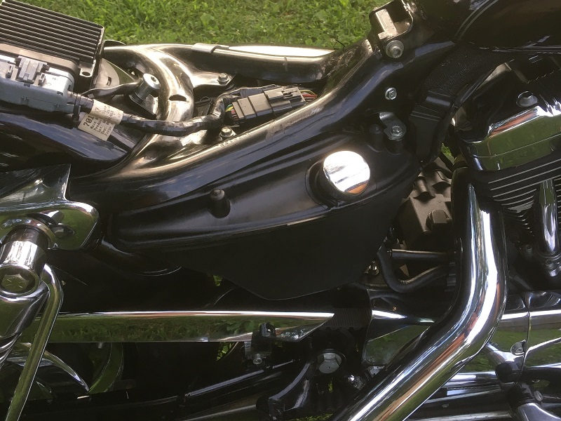
| 2007-2009 Sportster Oil Tank (62888-04A) 3) | ||
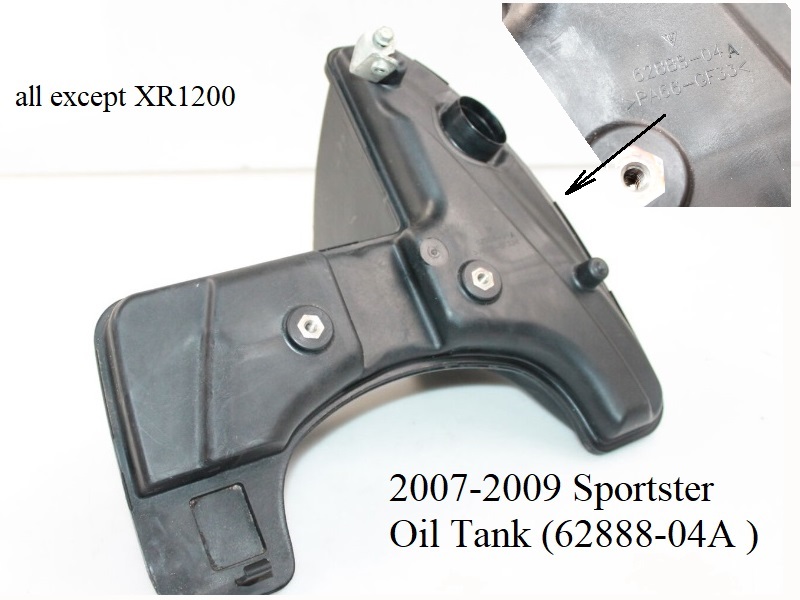 |  |  |
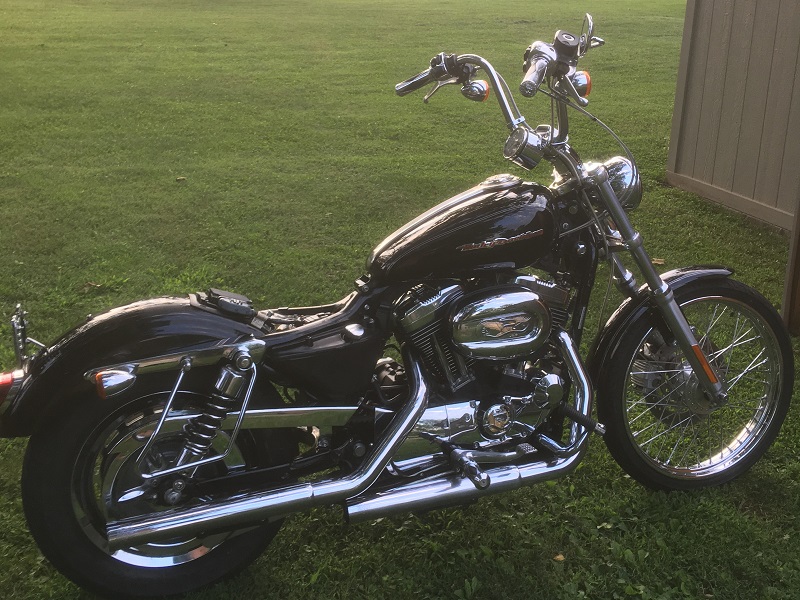
| 2007 1200C with 2010-2013 Oil Tank 6) | ||
 |  |  |
Oil Cap
04+ Oil Cap
These can be stubborn to turn all the way. You can use a little silicone lube on the O-ring to help it turn without binding.
Also a leather glove for grip helps. 7)
The threading tabs in the tank are molded in.
When installing the cap, it may stop at the first “bite” and not go any farther. The plastic cap has a void underneath which gives no support.
If the cap is difficult to turn in, it may have been inserted in the wrong position.
First, try to remove it and make sure the tab orientation is correct before re-inserting it in the tank (else it won't turn all the way 'home' and seal off the tank).
The metal cap with the analog gauge moves better as it is solid underneath the rim.
The pics below show the positions of the cap during installation.:


Oil Cap Repair
04 Style Oil Cap Repair
Article by JohnK of the XLFORUM 12)
If you've noticed your oil cap mysteriously popping up, it could be a broken internal sleeve.
One of the first symptoms is that the cap will not stay flush, but will protrude maybe an eighth of an inch above the tank surface.
Eventually it will not click down in place at all.
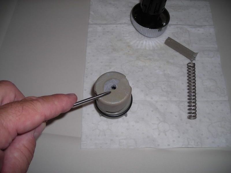
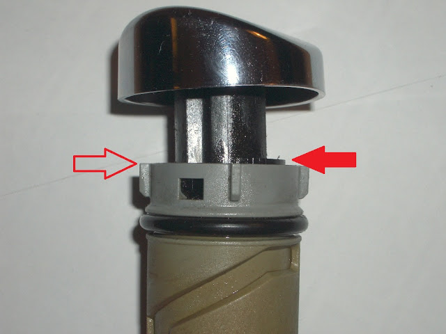
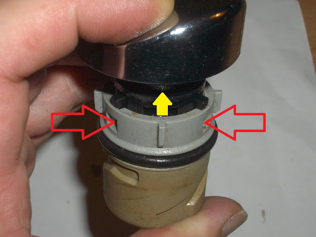
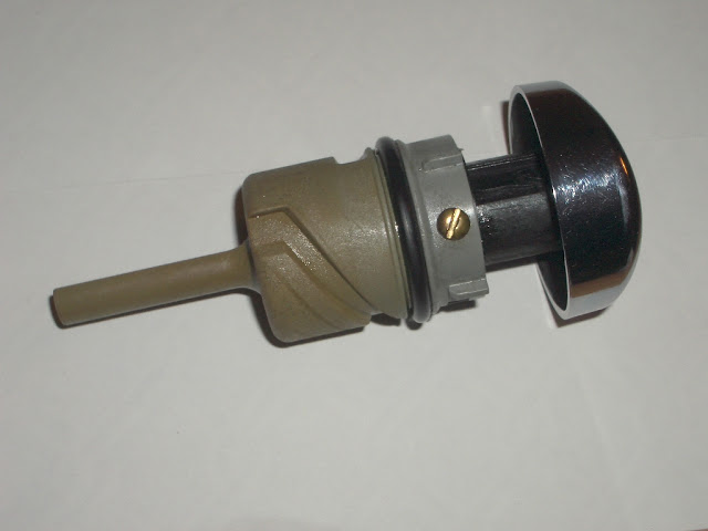
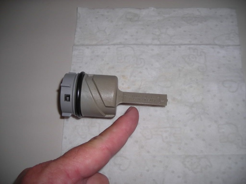
Take a close look just under the cap, where the plunger enters the body.
The black sleeve protruding above the grey body (in the right side arrow in the 1st pic below) may indicate a broken sleeve.
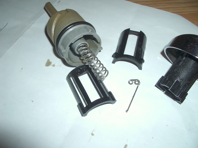
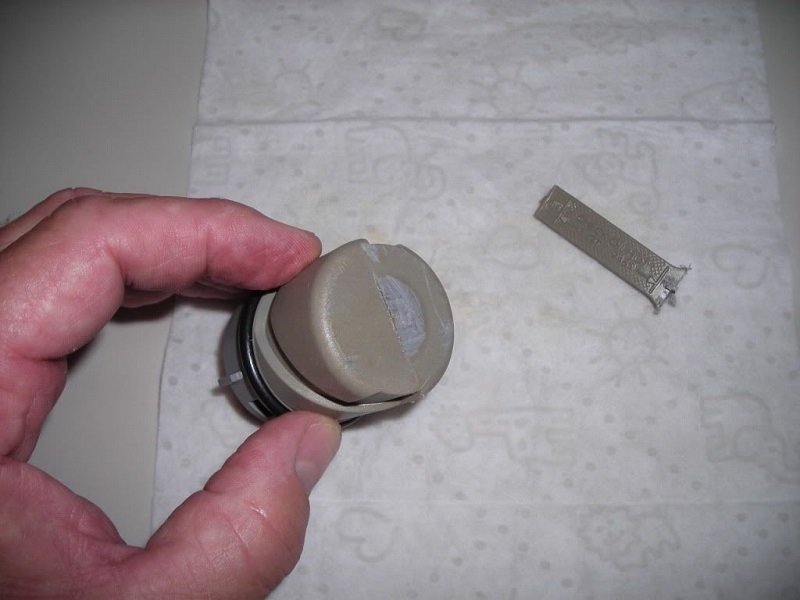
| The sleeve should be flush around the perimeter as shown by the left side arrow. 13) | To disassemble, find the two side square tabs and push each one in, and the mechanism will pop out under spring pressure. 14) | This is what you will have, notice the ratchet spring on the side, note how it fits for re-assembly later. 15) |
 |  |  |
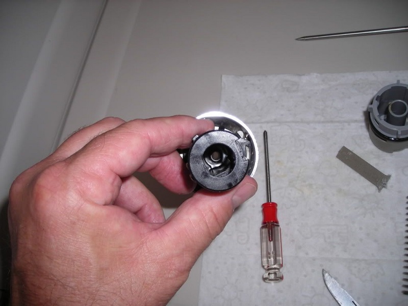
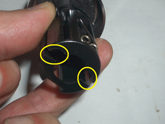
Now take a look at the bottom of the 'sleeve'.
It should be one piece.
The two halves are held together by two very thin sections of plastic on the bottom (as in the circled areas below).
In this case, the sleeve was broken into two pieces.
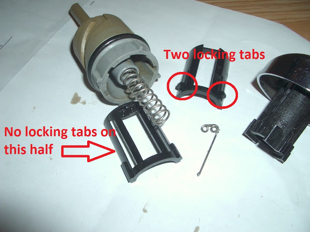
The locking tabs are both on one half of the sleeve, the other side is free to slide inside the body.
As long as the sleeve is joined together in one piece that's fine.
But the bottom thin section is prone to cracking.
(one side is locked and the other moves up and down ever so slightly each time the cap is popped)
Once this fails, the 'loose' side will protrude up as seen in the first pic above.
The side without the locking tabs is also the side with the ratchet spring.
(which adds additional up and down drag every time the mechanism is worked, accelerating the failure)
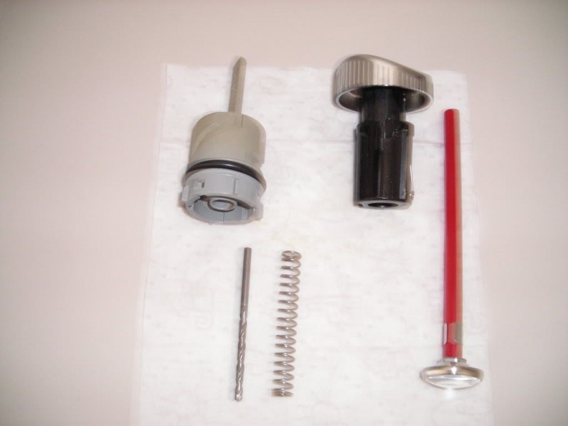
| The thin connecting material was broken out. 16) | Here are all the components, minus the broken out pieces. The sleeve is now in two halves. 17) | Note the locking tabs on one half of the sleeve and none on the other. 18) |
 |  |  |
The solution was to re-assemble the mechanism and install a set-screw to hold the loose side in place.
The entire operation shouldn't take more than an hour, if you take your time.
The only items required are a small screwdriver to push in the locking tabs, a set screw, an appropriate drill bit and drill.
You can find a small flat head screw, countersink the hole and drive the screw head flush for a better-than original look and function.
 19)
19)
Below, a brass screw from an electrical lug was used to screw through the grey plastic body and into the black inner sleeve.
It was short enough not to interfere with the moving plunger while long enough to screw through the grey plastic body to the sleeve.
Find a way to hold the sleeve down flush with the outer body and drill a hole slightly smaller than the screw thread.
Drill it right through both the body and sleeve.
It can be done with the plunger installed but it would be better to leave it out.
Drive the screw into the plastic, it will cut its own thread (that's why you drill a smaller pre-drill size hole).


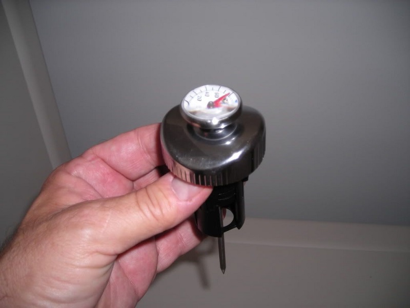
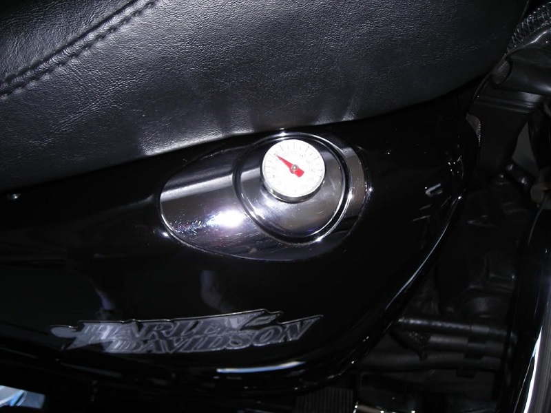
07 Style Oil Cap with Homemade Temperature Gauge
Article by ridinfool of the XLFORUM 22)
Sometimes you have to be innovative to save some cash.
This oil temp gauge was devised for about $20 as opposed to the $45 one from the MoCo.
Parts & Tools:
One meat thermometer either instant read dial or digit read.
Some JB Weld.
Drill / bit.
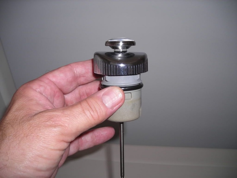
Take the oil cap apart as shown below.
Then cut the dipstick off flush with bottom of the cap.
Drill a hole just a bit smaller than the thermometer rod through the center so it fits snug.
Then drill a hole through the top of the oil cap.
Going through the bottom, there is a plastic piece that guides the drill bit.
Slide the meat thermometer in place with some JB weld on the bottom of it so it stays in place.
(make sure not to get the JB Weld on the rod itself as it needs to go up and down with the oil cap)