Table of Contents
This is an old revision of the document!

EVO: Engine Mechanicals - Sub-04J
Rocker Arm Inspection and Servicing
See also in the Sportsterpedia.
The forgoing is a compilation of maintenance and clearancing advice from the XLFORUM.
Most of these aren't mandatory unless you notice a problem upon inspection.
If problems are found, below are some examples of how those have been addressed.
The rocker arm shaft is not supposed to rotate from it's installed position.
The shafts have a notch in them that the bolt is supposed to butt up against which locks the rocker arm shafts in place. 1)
However, the bolt hole is too large which leaves a gap there.
This gap allows the shaft to slightly rotate and hit the bolt which causes an annoying ticking/tapping noise.
See the link above on Stabilizing Noisy Rocker Arm Shafts for more information in the Sportsterpedia.
Normally what should rotate is the rocker arm itself.
The bushings in the rocker arm pivot around the rocker arm shaft.
The shaft runs through bushings on both ends of the rocker arm.
These bushings can expand due to normal wear.
The FSM suggests visual inspection and measuring of specific clearances as outlined below as a guide to when to replace parts.
Ultimately, it's an individual judgment call as to replacing parts that are within measured specs.
Rocker Arm Specs
Service wear limits are a guideline for measuring parts that are not new.
Replace parts when their measurements exceed the wear limits below.
If wear limits are not given for a part, refer to the new install specs. 2)
 |
||
|---|---|---|
| Rocker Arm Specs | New Install | Used Service Wear Limits |
| Shaft in bushing (loose) | .0005“ - .0020” (.013 mm - .051 mm) | .0035“ (.089 mm) |
| End play | .003” - .013“ (.08 mm - .33 mm) | .025” (.64 mm) |
| Bushing fit in rocker arm (tight) | .004“ - .002” (.10 mm - .05 mm) | No variance |
| Rocker Arm Shaft Specs | New Install | Used Service Wear Limits |
| Shaft fit in rocker cover (loose) | .0007“ - .0022” (.018 mm - .056 mm) | .0035“ (.089 mm) |
Inspection before removal
Check the end play of each rocker arm
The ends of the rocker arms can wear down the area where they touch the lower rocker box.
- Push the rocker arm to one end.
- Check the clearance between the other end and the cover with a feeler gauge.
- The FSM suggests to replace the rocker arm or lower cover or both if the end play exceeds .025” (.63 mm). 3)
| Checking end play 4) | |
Check Arm Contact at Valve Spring
Inspection after removal
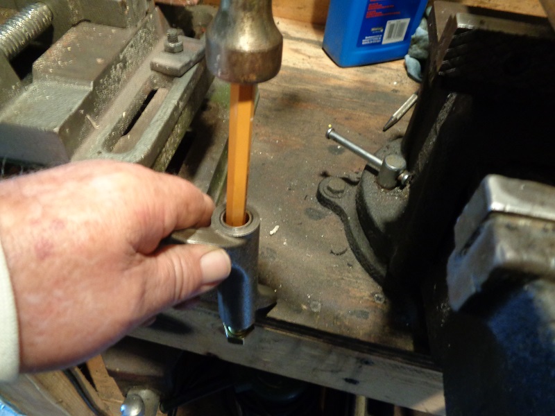
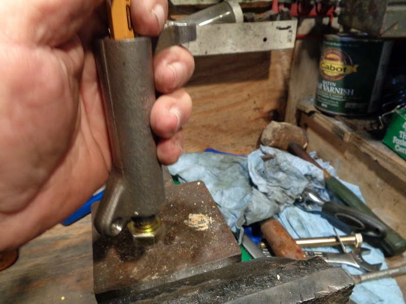
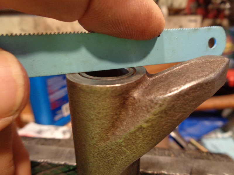
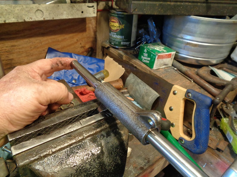
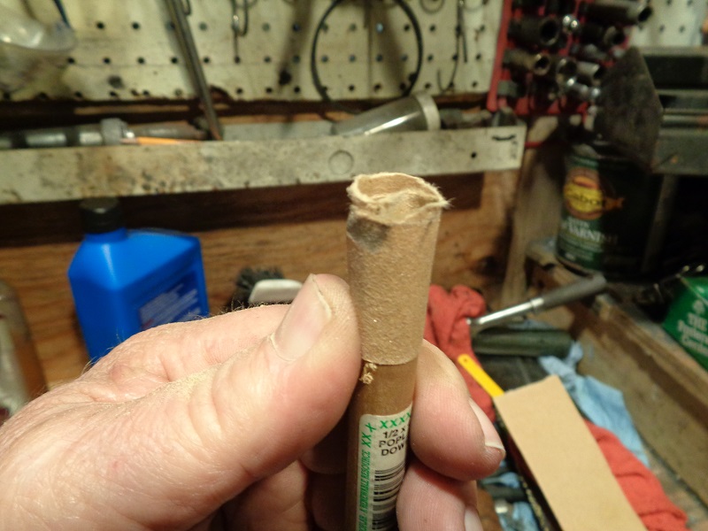
If the rocker arm shafts will not slide out on their own;
You can remove them by tapping them out using a hammer and a soft metal punch. 7)
 |  |  |
You'll be measuring for an 'out of round' condition of the rocker arm and associated parts.
Most of the wear in the rocker arm shafts and bores results from up and down movement of the pushrods and valves. 8)
This can result in an out of round condition on either or all of these parts.
(more wear in the top and bottom than the sides)
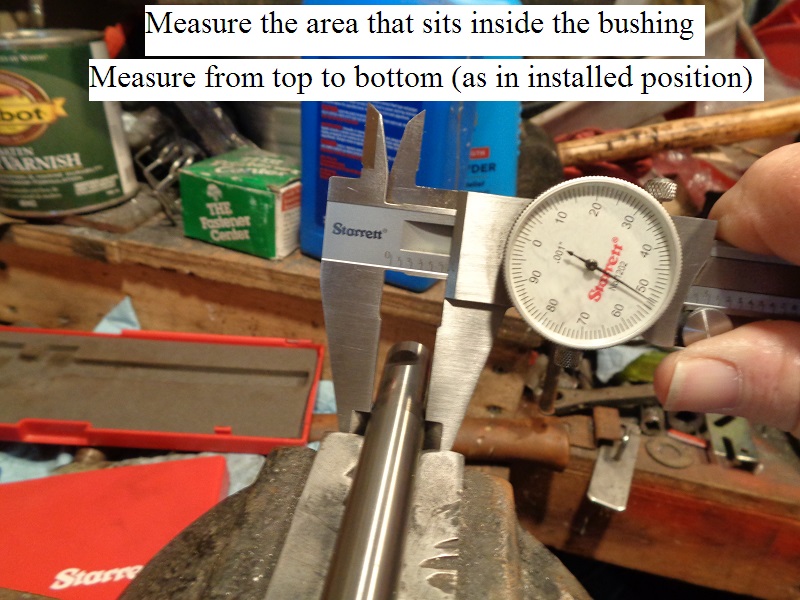
When measuring the rocker arm shaft end, it's bushing or cover bore when new,
Take a measurement and then turn 180° and take another measurement.
The two measurements should be the same in newly installed parts.
Subsequent wear will happen from top to bottom and need replacement.
This could induce noise and expedite wear on the parts.
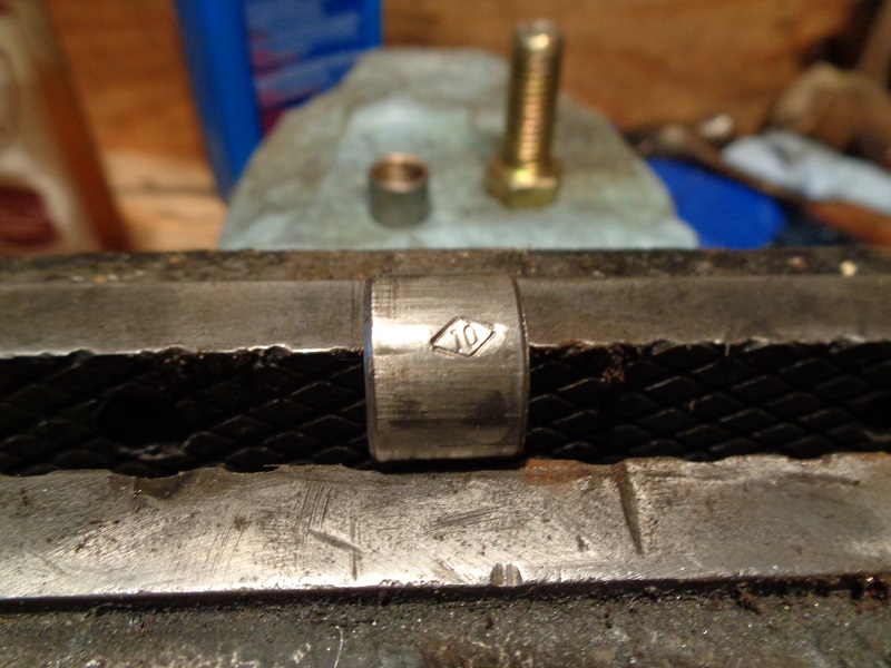
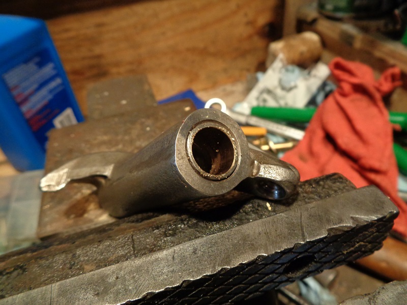
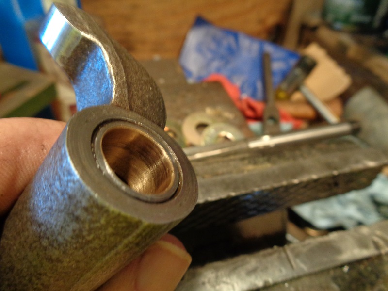
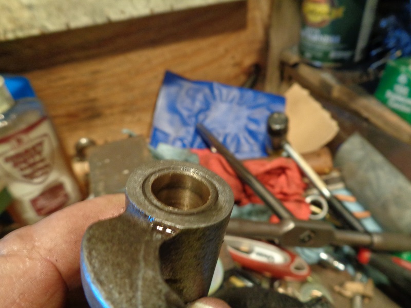
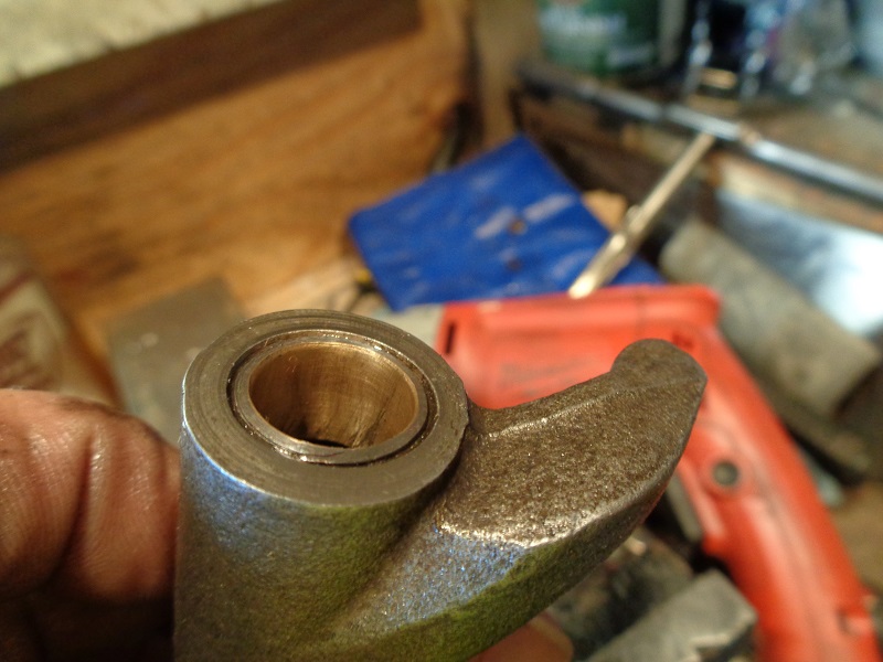
Check the shaft in bushing clearance
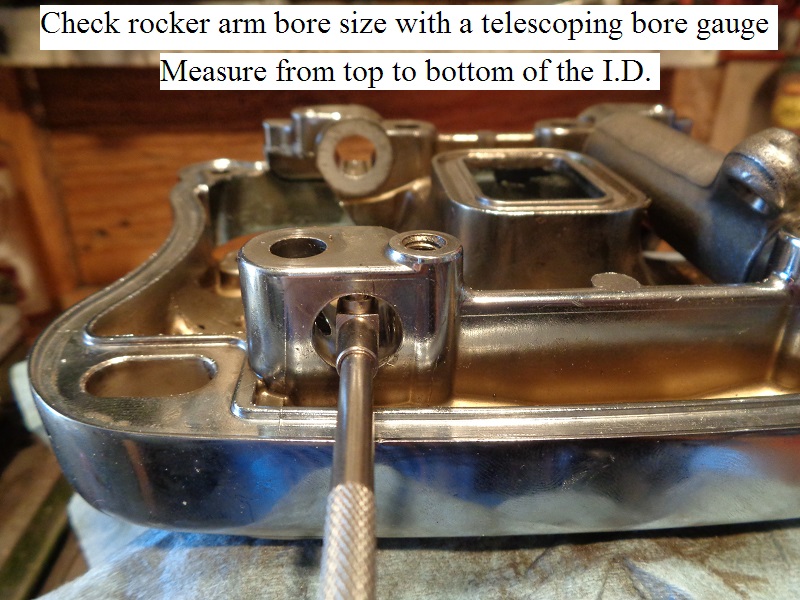
All measurements should be taken from the top to bottom position as each part sits while installed as per the FSM.
Both arms on each rocker are being pushed upward during operation.
The load side is on the bottom. That is where most of the wear will be as in the pic below.
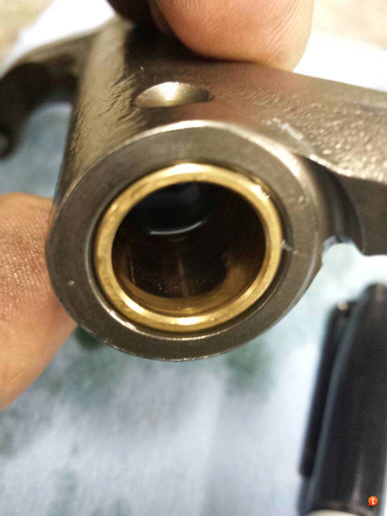 9)
9)
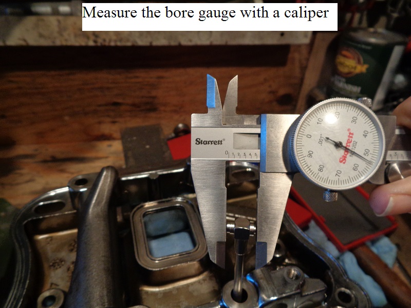
- Measure and record the rocker arm shaft dia. at each bushing area with a caliper.
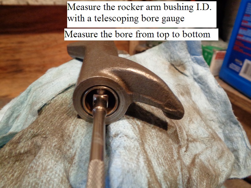
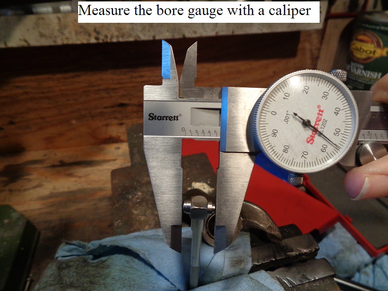
- Measure and record the I.D of the rocker arm bushing with a telescoping bore gauge and caliper.
- Subtract the shaft dia. from the bushing I.D. and match that number against the wear limit specs.
- If the bushing is at or past the service wear limit, proceed to “replacing the bushings” as in below.
 |  |  |
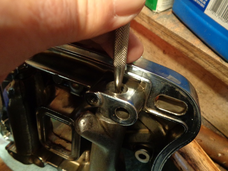
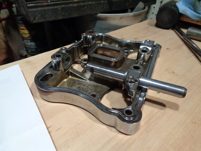
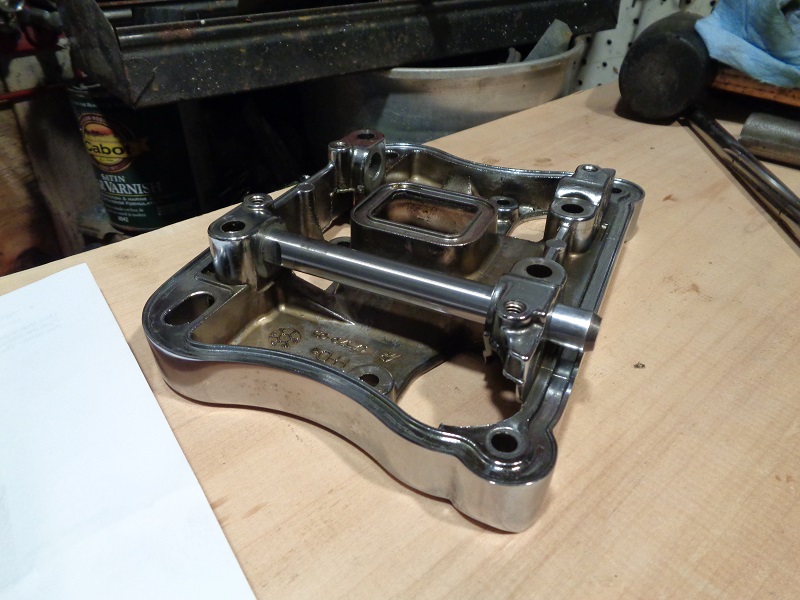
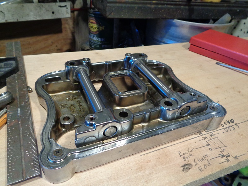
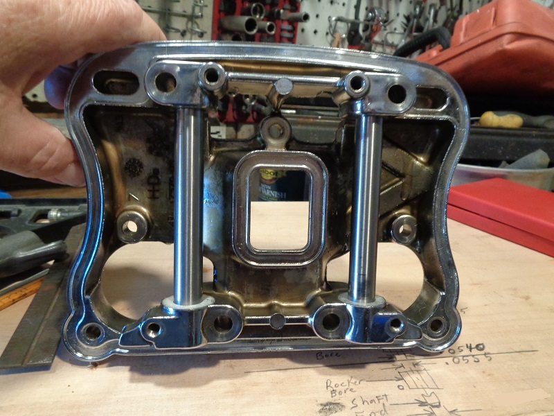
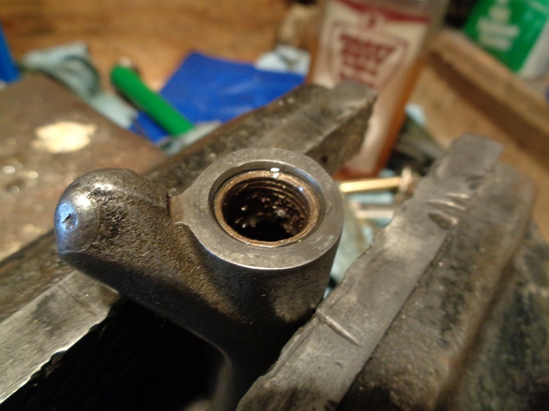
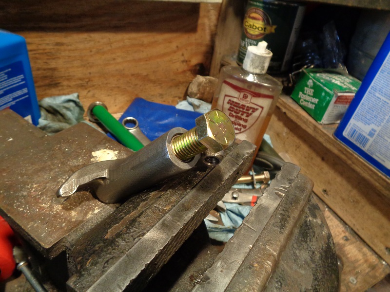
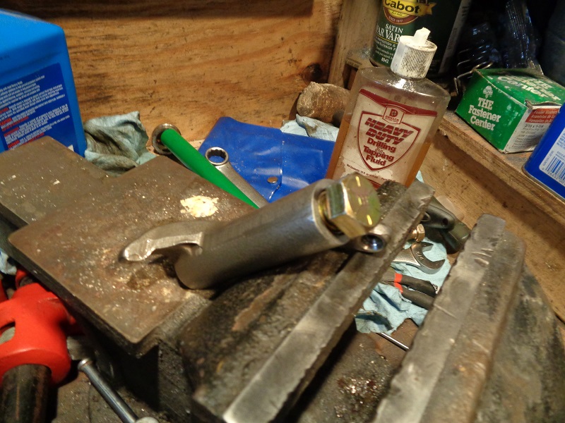
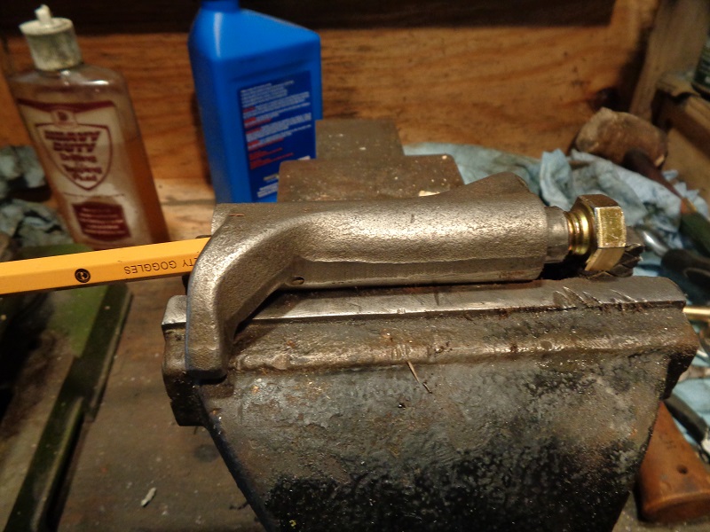
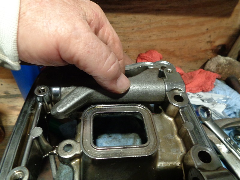
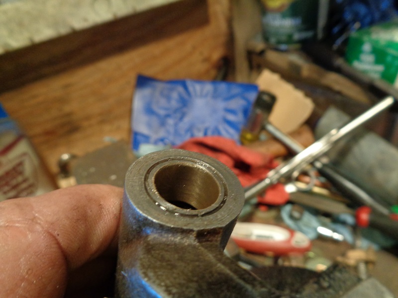
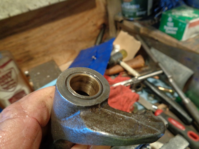
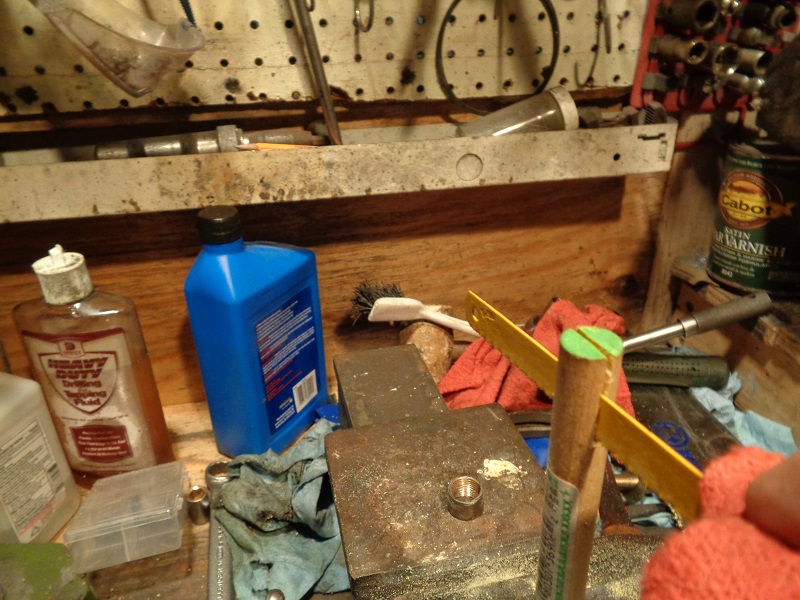
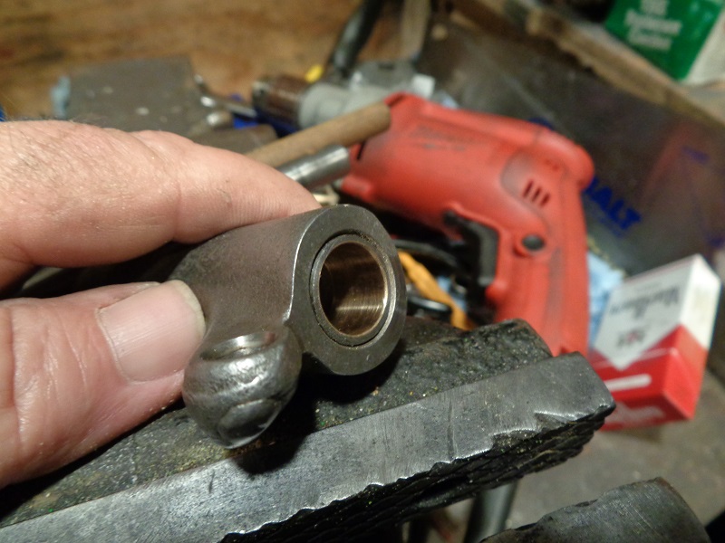
Check the shaft fit in the rocker cover
An assembly bolt runs through the gap near the end of the shaft.
The gap is wider than the bolt.
This allows a slight movement of the shaft in it's rocker cover bore.
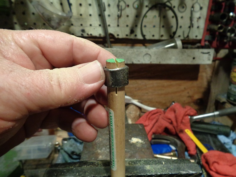
You can check for slight movement there on a running engine: 10)
With the covers off, draw a straight line with a felt marker on the end of the shaft from the cover bore and down the shaft.
Then fire up the engine. At idle, if you see any back and forth movement of that line, you have movement of the shaft.
Checking the shaft fit is the same as checking the bushing clearance;
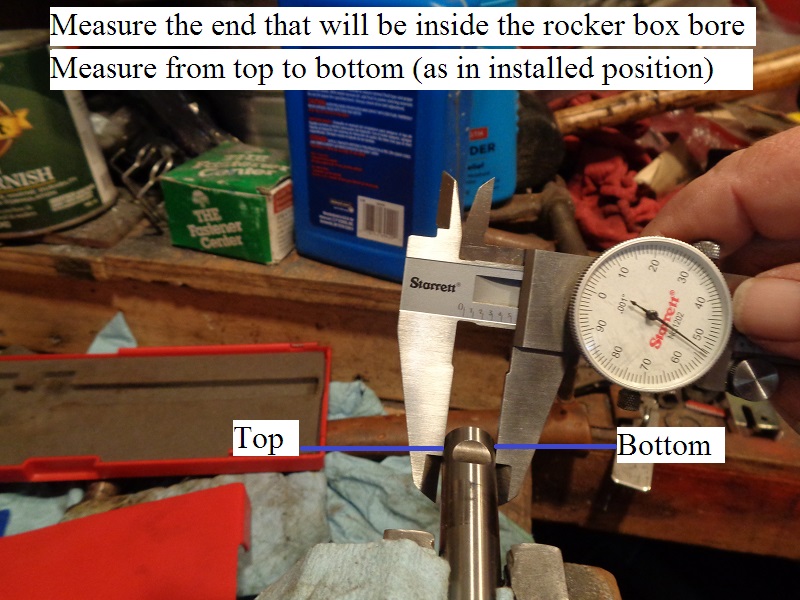
All measurements should be taken from the top to bottom position as each part sits while installed as per the FSM.
That is where most of the wear will be as mentioned above.
- Measure and record the dia. of the rocker arm shaft at each rocker bore with a caliper.
- Measure and record the I.D of the rocker box bore for the shaft with a telescoping bore gauge and caliper.
- Subtract the shaft dia. from the rocker box bore and match that number against the wear limit specs.
- If the either are at or past the service wear limit,
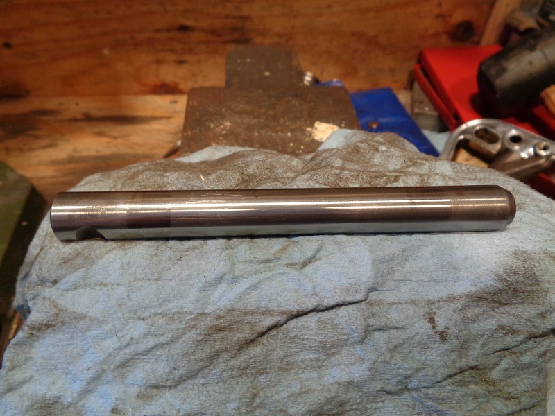
- Check the dia. in the middle of the shaft against the dia. at the end. Both places should be the same.
If the shaft is smaller in dia. on the end, replace the shaft and recheck the measurements.
(this is cheaper than replacing the lower rocker cover) - If the shaft mic's out OK, then replace the lower rocker cover.
 |  |  |
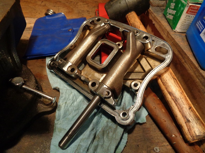
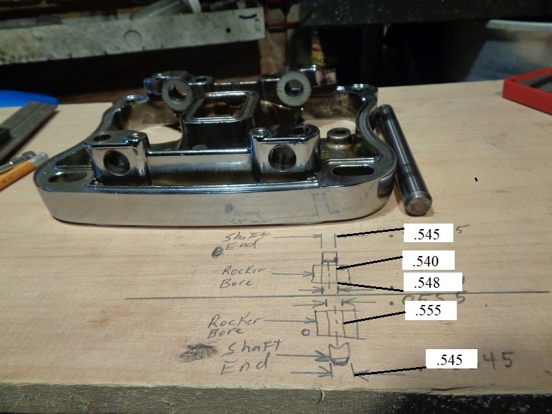
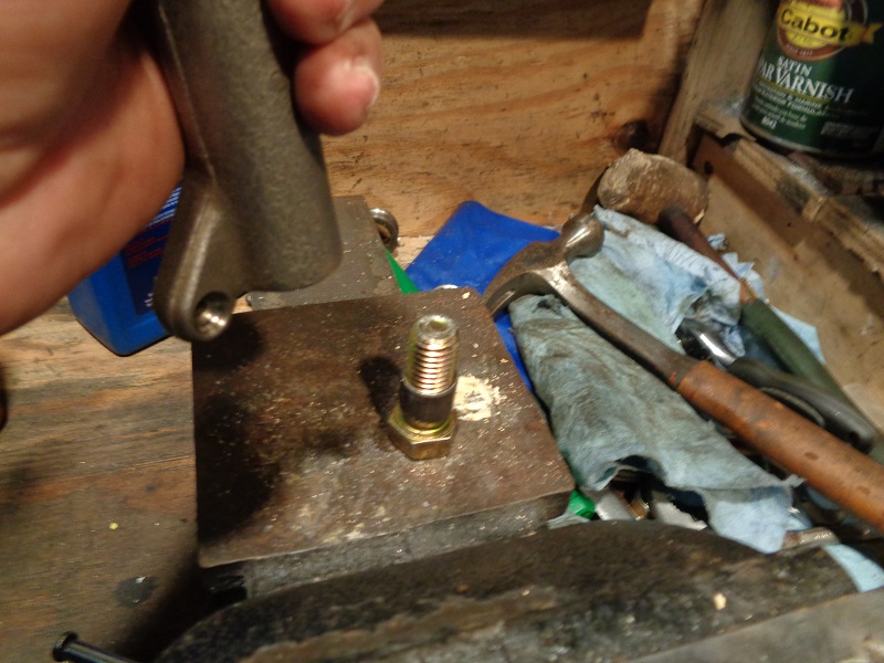
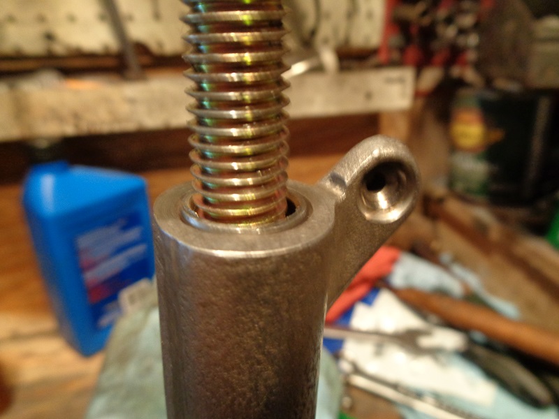
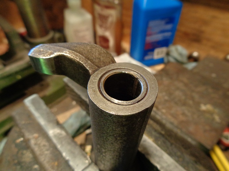
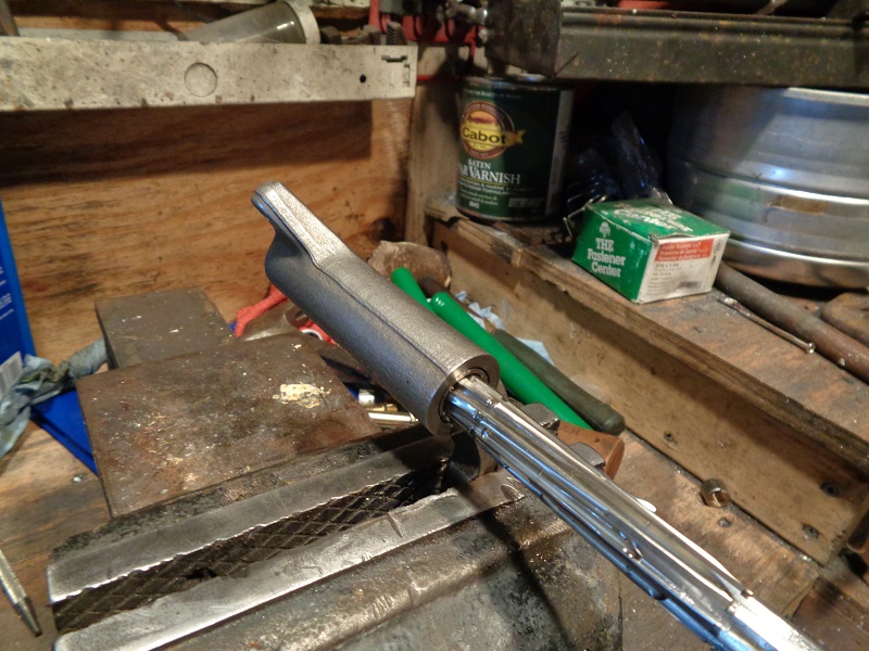
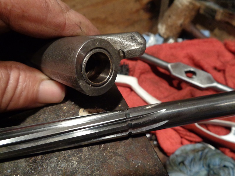
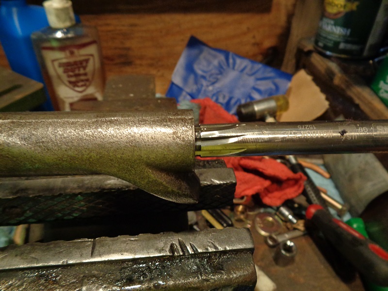
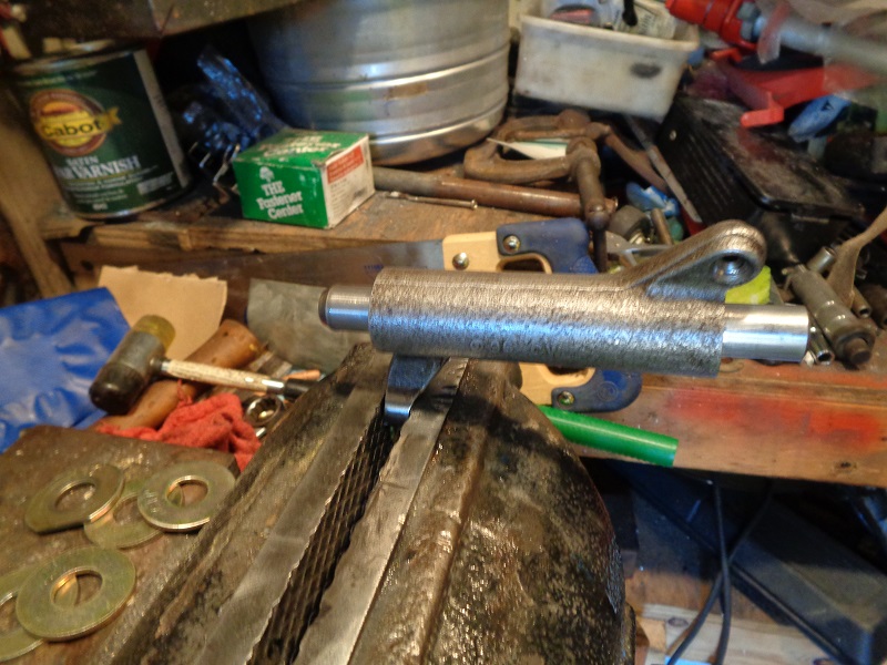
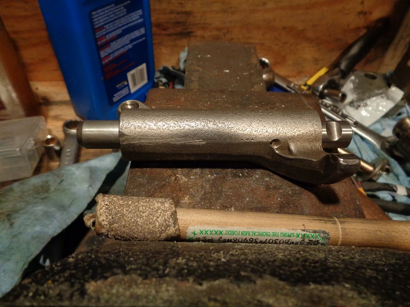
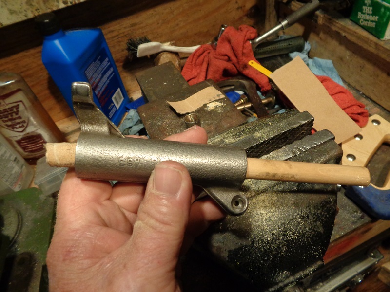
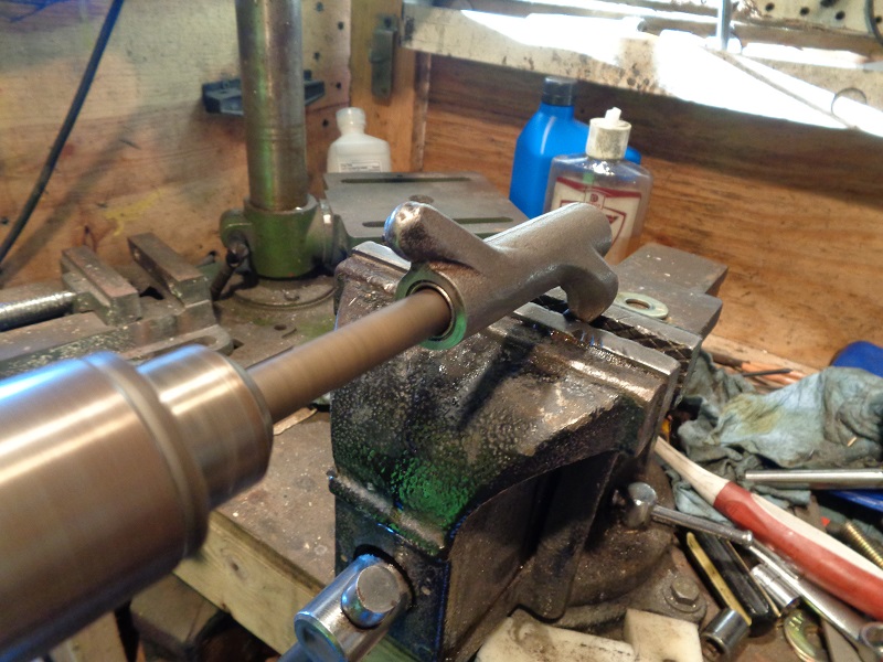
- The shafts below were test fitted to find where the binding was happening.
One end of each shaft slid in easily on one side but would bind up going into the other end. - There was app. .001“ clearance on the chamfered end and a press fit on the other.
- Per the specs in the FSM;
Shaft fit in rocker cover (loose)
New Install .0007” - .0022“ (.018 mm - .056 mm)
Wear Limits .0035” (.089 mm)
There was not enough clearance on one side (as the dims show in the pic below).
 |  |  |
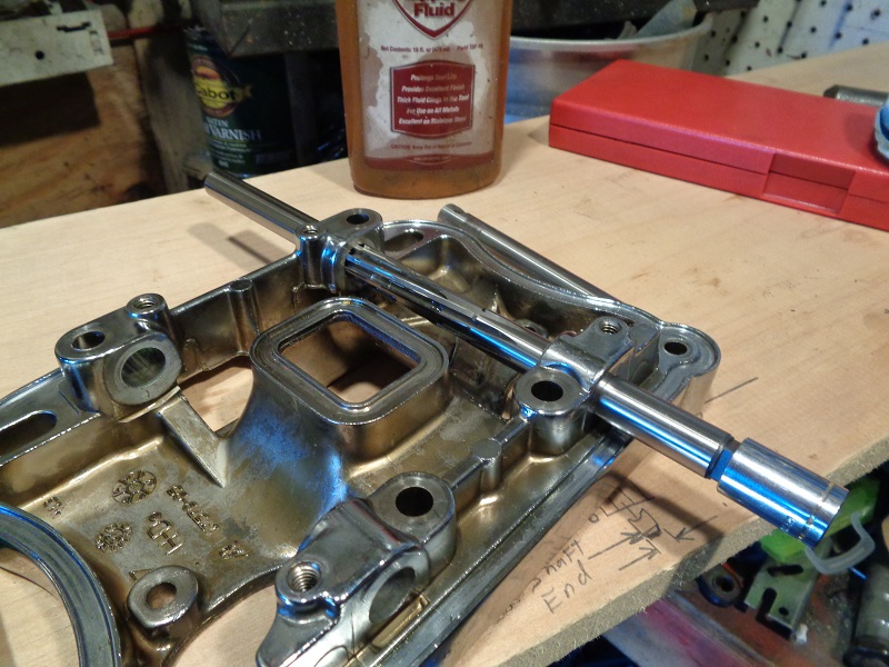
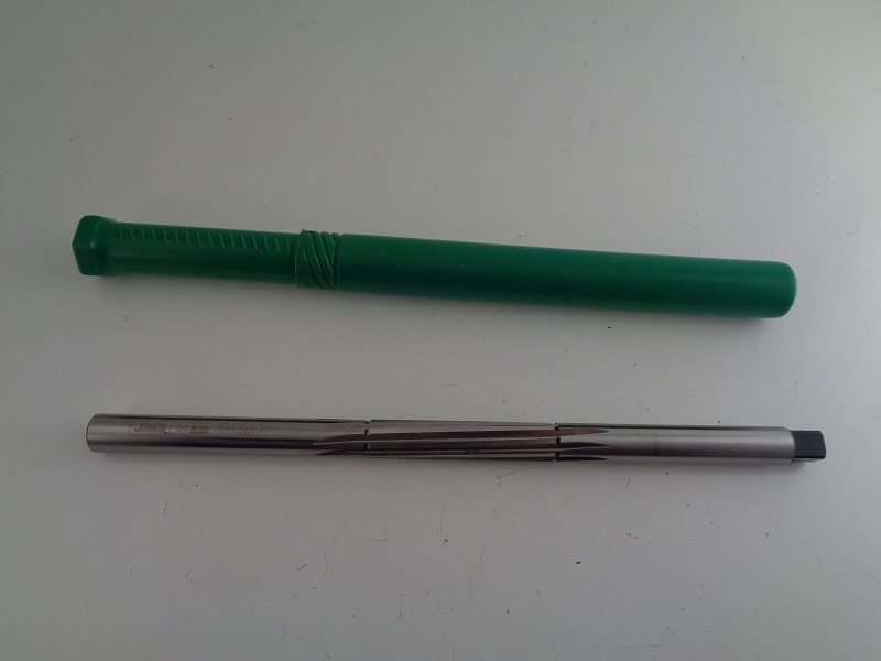
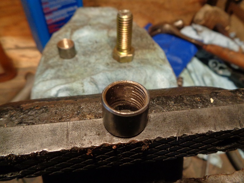
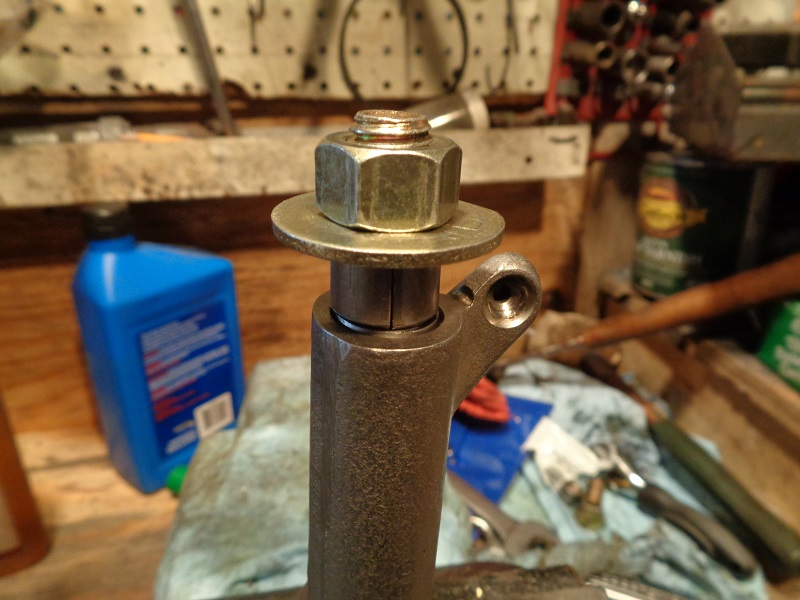
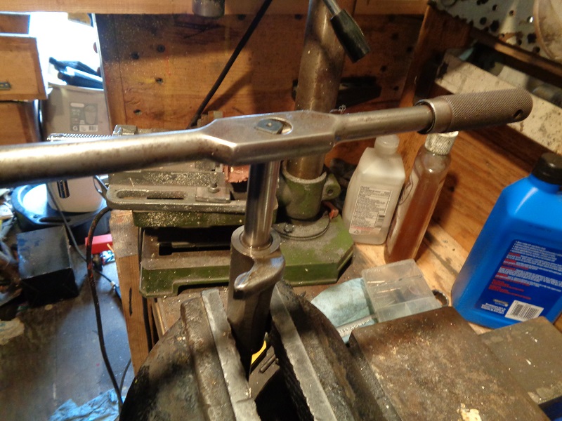
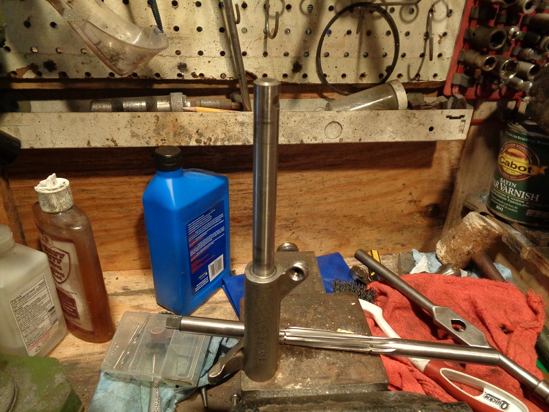
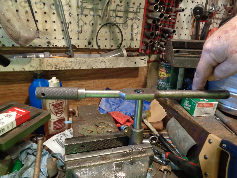
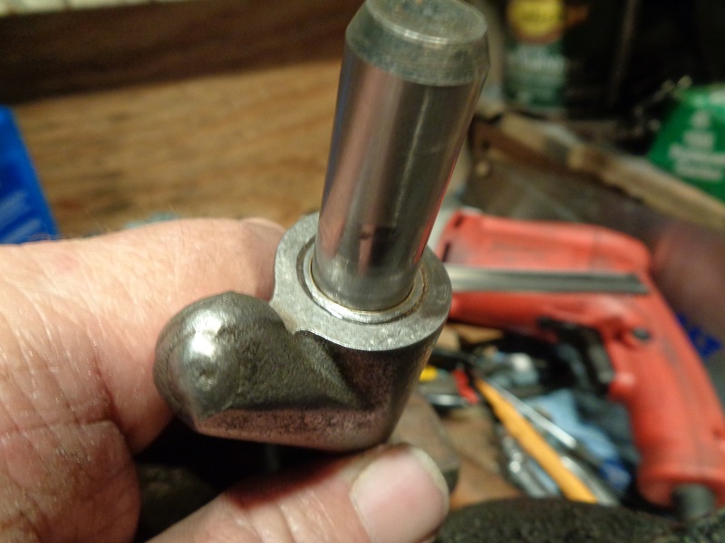
- The Jims reamer (94804-57) was used to run through the loose side to square up the hole for reaming on the other.
A 12-point 12 mm socket was used as a finger hold to turn the reamer in by hand.
(turning slowly by hand to let the reamer do the cutting) - Continue until the reamer makes it to the end and push it out.
- Then clean the shavings and run it back thru to make sure you got a uniform cut.
 | 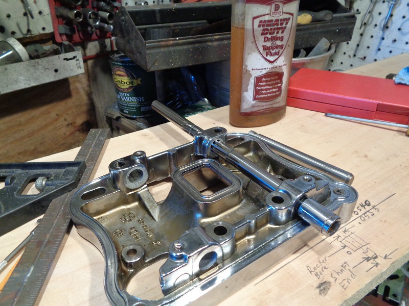 | 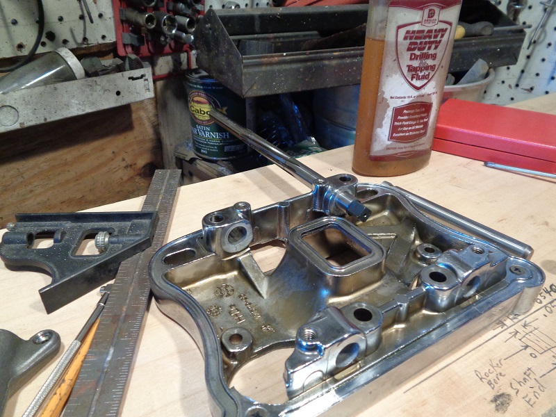 |
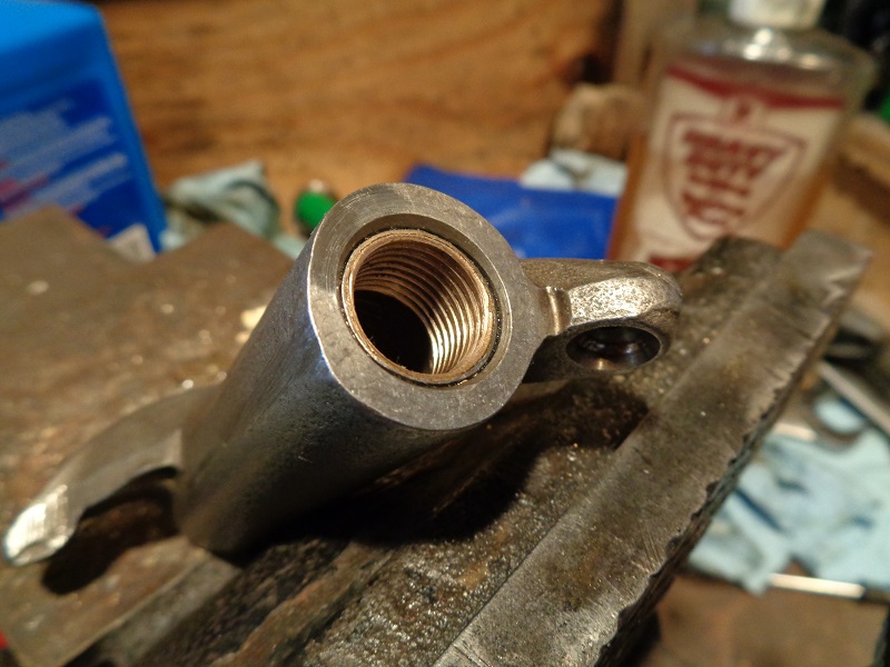
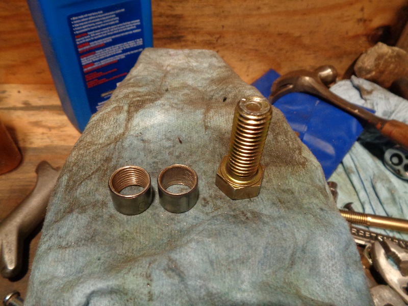
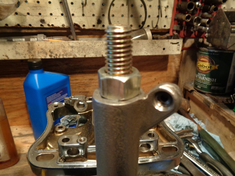
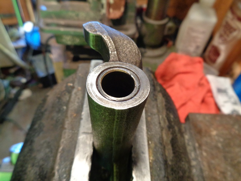
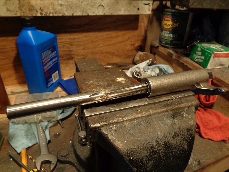
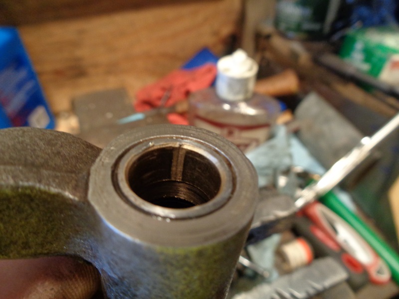
- When done, the shaft slid into both ends evenly with no slack.
The smaller bore mic'd out to .555” which is the same as the other side now. - At ambient temperature of 54°F, the shafts would not slide out on their own with the rocker box turned vertical.
 |  |
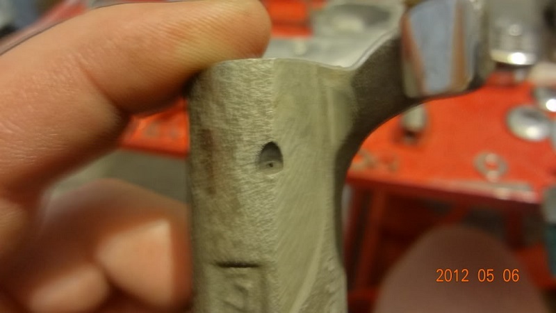
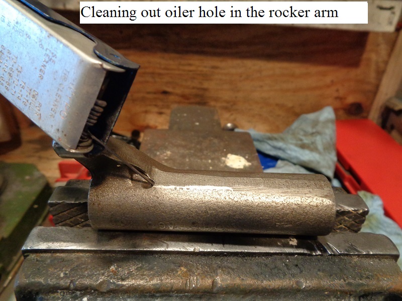
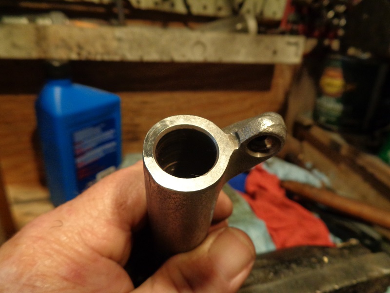
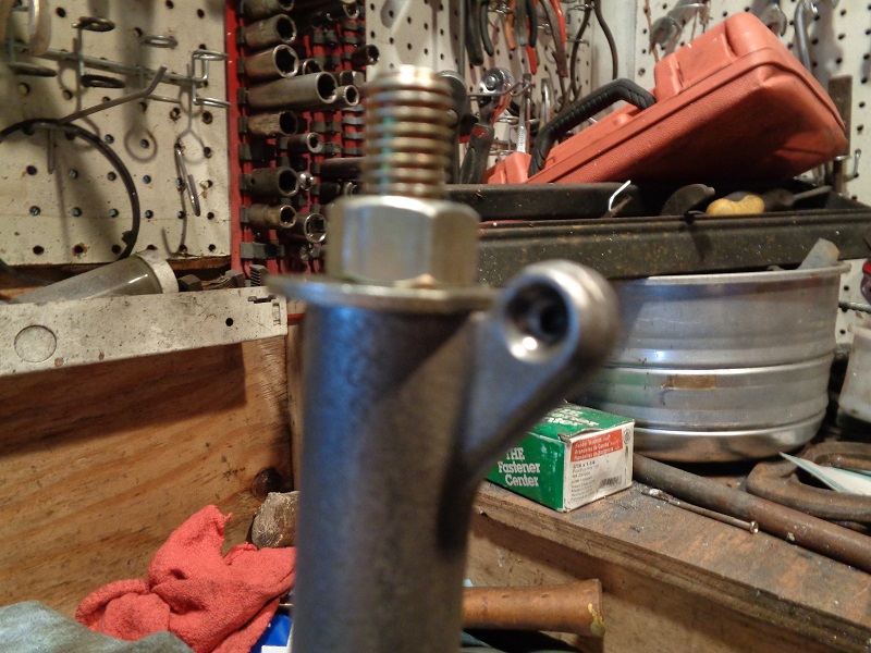
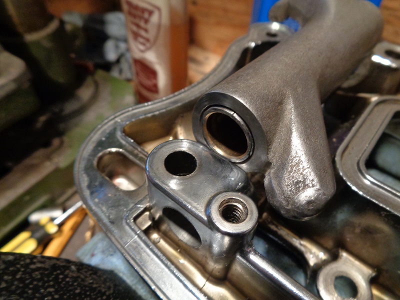
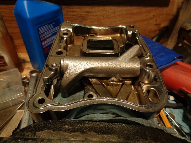
Check the valve oiler hole in the rocker arm
The valve side arm has one tiny little hole that the intake rockers don't have. 11)
This tiny little hole is for extra oiling for cooling the valve(s).
While you have the rocker arms out,
You can use a welding tip cleaner or other small wire to poke down this hole to clean or verify the hole is clear.
Visual Inpections
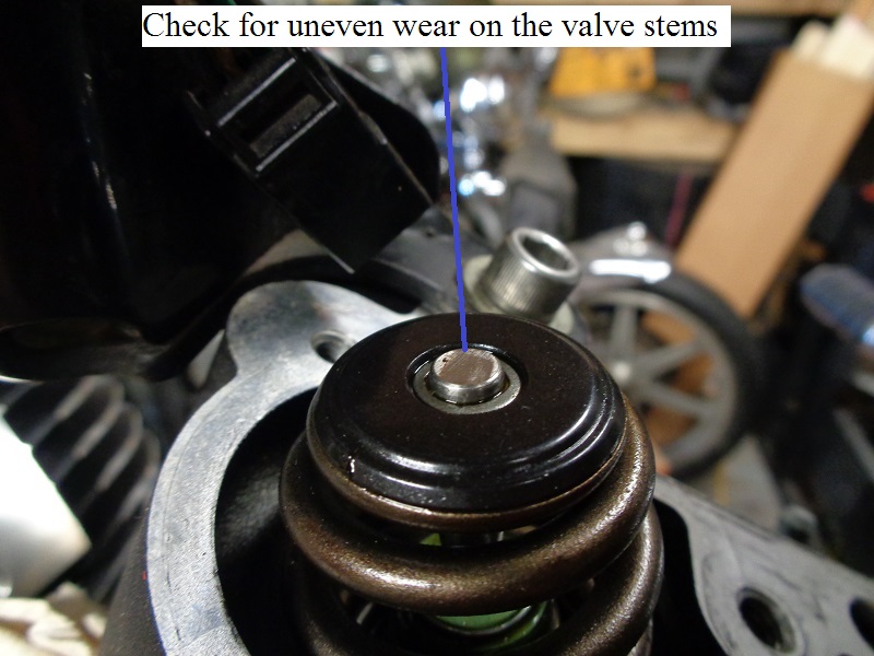
Inspect the valve stems
- Look at the condition of the valve stems in the heads.
This will give you an indication of how the rocker pad is wearing against the valves.
Check for pitting or uneven wear.
 |
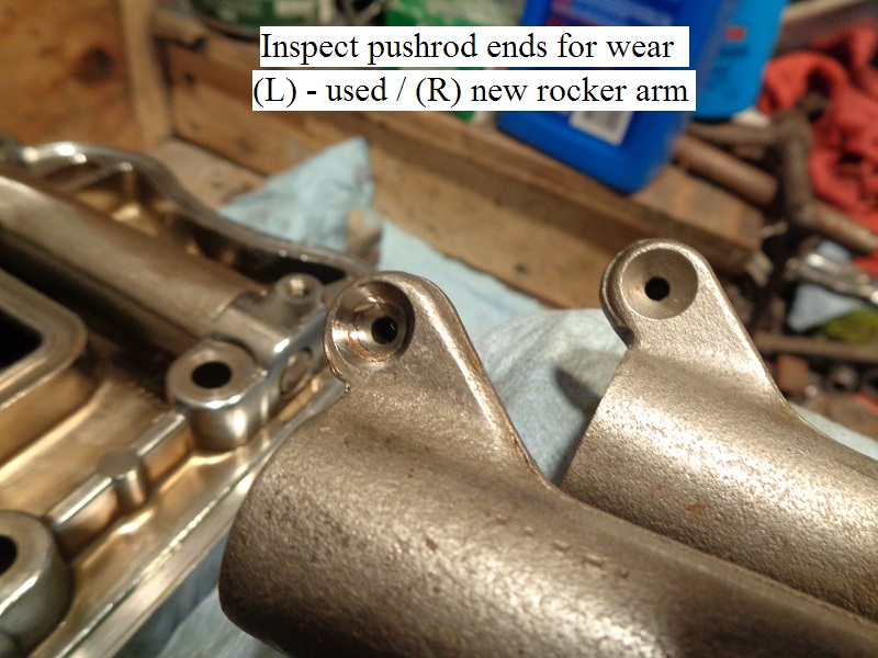
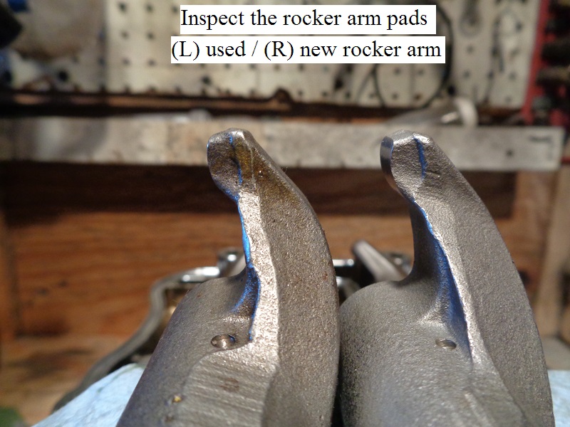
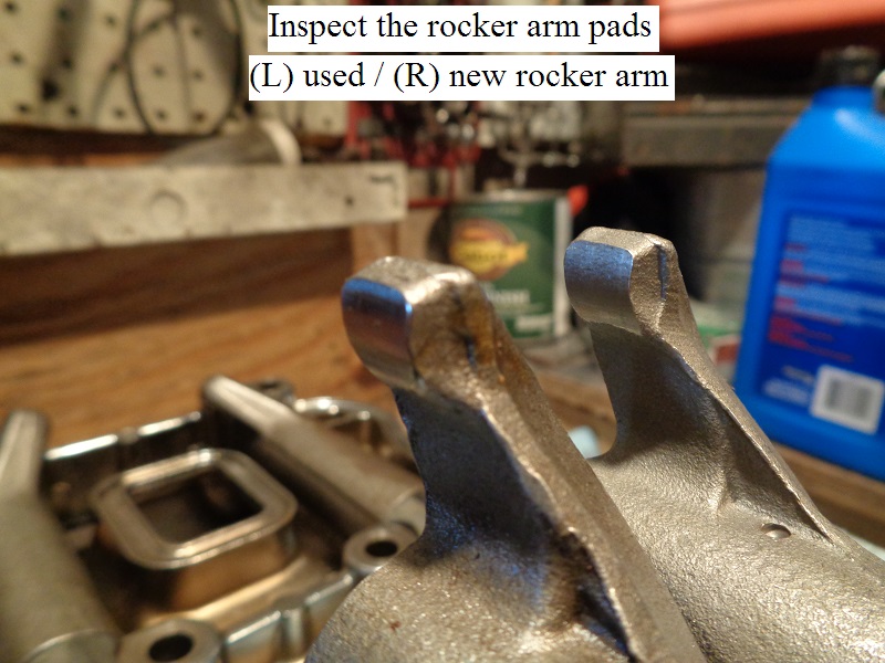
Inspect the rocker arm ends
- Inspect both the rocker arm pad and pushrod end for uneven wear or pitting.
Replace the rocker arm if either exist.
 |  |  |
Rocker Arm Bushing Replacement
Note: The bushing reamer (94804-57) has right hand blades. Always turn it to the right (clockwise) when installing, reaming or removing it from the bushings.
A helpful suggestion is to mic the bushings closely and several times to be sure you need to before replacing them. 14)
If the rocker arm pads or the pushrod cups are worn badly, it'd probably be best to just replace the arms instead.
New rocker arms come with the bushings installed and sized.
Specs: Shaft in bushing (loose)
New install: .0005” - .0020“ (.013 mm - .051 mm)
Service Limit: .0035” (.089 mm)
It's not common to have to replace the rocker arm bushings. 15)
Unless you run them dry or put high lift cams in causing them to hit the boxes, you shouldn't have an issue with them.
The bushings may wear eventually, but that should be well in to the 100k territory.
I don't know anyone who has worn one out.
As far as rocker arm bushings, where they're made isn't nearly as important as having them installed and fitted correctly. 16)
Replace the rocker arm bushings one at a time.
Tools
For bushing removal
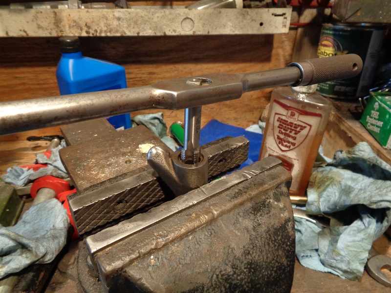
Basically, you'll need to tap 9/16“ threads in the bushings so you can thread a bolt in there and knock the bolt out with a punch, carrying the bushing with it.
As an alternative, you can use a longer bolt and use a press to push the bolt/bushing out.
It's a good idea to use a bolt to hit / press against instead of the tap since the tap can break then you'll have to thread a bolt in anyway.
Then you'll have wasted a tap and possibly destroyed the threads you just cut.
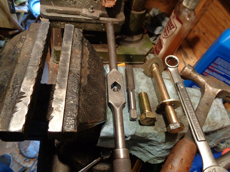
- Basic tool list:
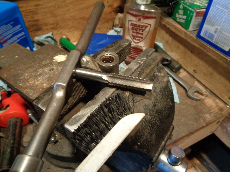
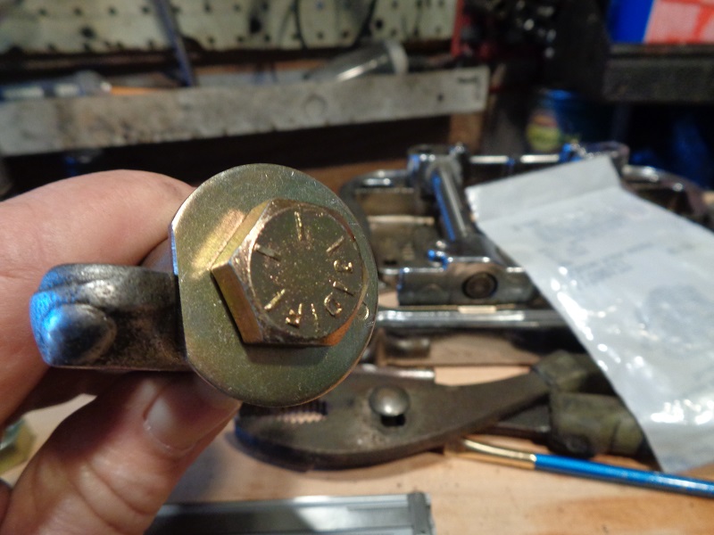
- (1) 9/16”x18 tapered thread tap
- (1) 9/16“x18x1” grade 8 bolt (3/4“ to 1-1/2” length will work)
- (1) tap wrench to fit the 9/16“ tap
- (1) drift or punch
- (1) Hammer
For bushing installation
You can use a long 1/2” bolt / nuts and washers as a press to pull the new bushings into the rocker arm.
Or you can an arbor press or shop press to pull them in also.
- Nut / Bolt Press:
- (1) 1/2“x13x5” grade 8 bolt
- (2) 1/2“ grade 8 washers
- (1) 1/2” grade 8 nut
- (1) 3/4“ box end wrench
- Arbor Press or Shop Press:
- You can make an arbor button that will fit the bushing with a stop shoulder, could be any length. 17)
That way, the ID is protected from the threads and with the stepped shoulder, press it home until it stops.
The arbor button could be a right sized bolt with a long shank with the threads cut off. This would negate the need for turning one on a lathe.
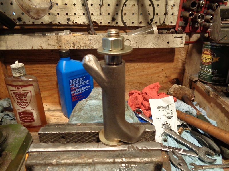
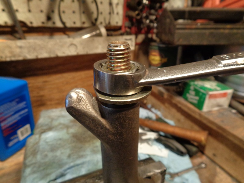
- Using a Bench Vise:
- A standard bench vise isn't the best idea, but if your vise opens wide enough, you could try it as a press with an arbor button as mentioned above. 18)
- However, keep in mind that most bench vises do not have a dedicated flush pull though. 19)
The jaws will pull closer together on the opposite side of where the piece is clamped.
So the rocker arm would need to be placed in the center of the vise to help ensure a center pull on the bushing to keep it from binding / distorting.
Then pull the bushing in slowly checking for binding as you go. It will get tight once the bushing gets about halfway home.
For bushing reaming / sizing
- Using the JIMS rocker arm bushing reamer:
- JIMS reamer (94804-57) is quite expensive at a current average of $267. But it works very well.
It is used with a hand tap wrench or socket wrench.
- Using a Chucking reamer:
These are less expensive but there are considerations for using one.
This is a non tapered reamer with a small chamfer on the end and is shorter than a tapered reamer.- This type reamer is best used in a milling machine.
- It can be used to hand ream but only if you have a centering fixture like a sleeve bushing inserted in the opposite end of the rocker arm.
The hole has to be centered from one bushing thru to the end of the opposite bushing. - It can be used with a hand drill on low speed. Non tapered reamers cut on the chamfered end and center around the cut they just made.
If it bites more to one side or the other, especially on the initial cut, the rest of the ream job won't go well.
A extra sleeve bushing for the reamer shaft is a must for using this type reamer for these bushings.
- Line Lapping (if necessary):
- (1) 1/2”x12“ wooden dowel
- A few small pieces of sandpaper:
- 60 grit, 220 grit, 400 grit, 1500 would be good to have on hand depending on how the reaming goes.
Procedure
Remove the existing bushing
- Press or drive one bushing out of the rocker arm while leaving the other in place.
- The 9/16”x18 tap is used to cut threads into the bushing to give you something to bite into it and knock or press it out from inside out.
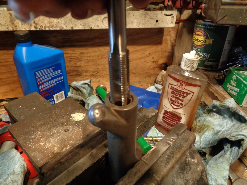
- Stand the rocker arm into a bench vise while just snugging the vise around the arm.
- The vise won't hurt the hardened rocker arm.
- Spread some tapping oil on the 9/16“x18 tap.
- Thread the tap into the bushing.
- The taper will allow you to center up the tap as best as possible before cutting the threads in the bushing.
- The bushing will be 'out of round' by default of needing to be replaced.
- Likewise, the threads you'll be cutting into the bushing will not be perfect.
- As long as the bushing will take threads, this will work.
- While tapping the bushing, hold slight pressure downward (or inward) to keep the tap from sitting and spinning.
- If it spins without continued cutting, it will remove the threads it just cut.
(if this happens too far into the bushing, the new threads will be useless in removing the bushing) - Thread the tap in far enough to cut threads on the full length of the bushing.
- The tap won't be long enough to affect the existing bushing in the other end.
- Remove the tap, clean the new bushing threads and install the 9/16”x18 bolt for the length of the bushing.
- The bolt is used in place of the tap to keep from damaging the tap while knocking the bushing out.
(the bushing can also be pressed out using a drift on the bolt as well)
- Then, from the opposite end, press or knock the bushing out of the rocker arm using a drift or punch.
- The rocker's arm can be set on a wooden corner with the shaft bore hanging off the edge.
- Then place the drift into the opposite end and hit downward with a hammer.
- It takes a couple good strikes to knock the bushing out about halfway.
- Then you can hold the assembly in one hand and gently finish tapping the bushing out.
| Thread the lubed tap into the bushing. 23) | ||
 |  |  |
| Clean the threads in the bushing for the 9/16“ bolt. The vise won't hurt the rocker arm. 24) | ||
 |  |  |
| Run the 9/16” bolt in for the length of the bushing. It takes a couple good hits to initially move the bushing. 25) | ||
 |  |  |
| Once the bushing pops out about halfway, you can use softer blows to finish removing the bushing (and not drop and ruin the bolt threads). 26) | ||
 |  |  |
| The newly cut threads will be damaged once the bushing is removed. This makes the initial threading important for best results. 27) | ||
 |  |  |
Install the New Bushing
- Press the replacement bushing into the rocker arm flush with the arm end.
- Place the split portion of the bushing towards the top of the arm.
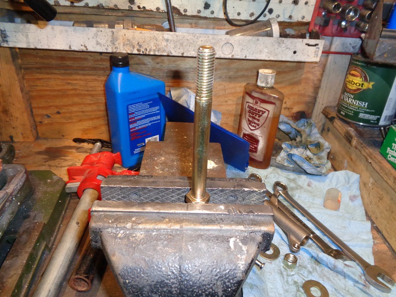
- The 1/2“x13x5” bolt was used below to pull the new bushing into the rocker arm bore.
| Clean the bore of all oil and debris. Actetone or brake cleaner works well. 28) | |
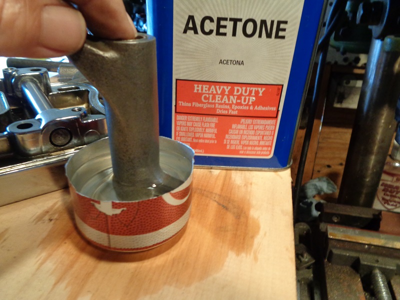 |  |
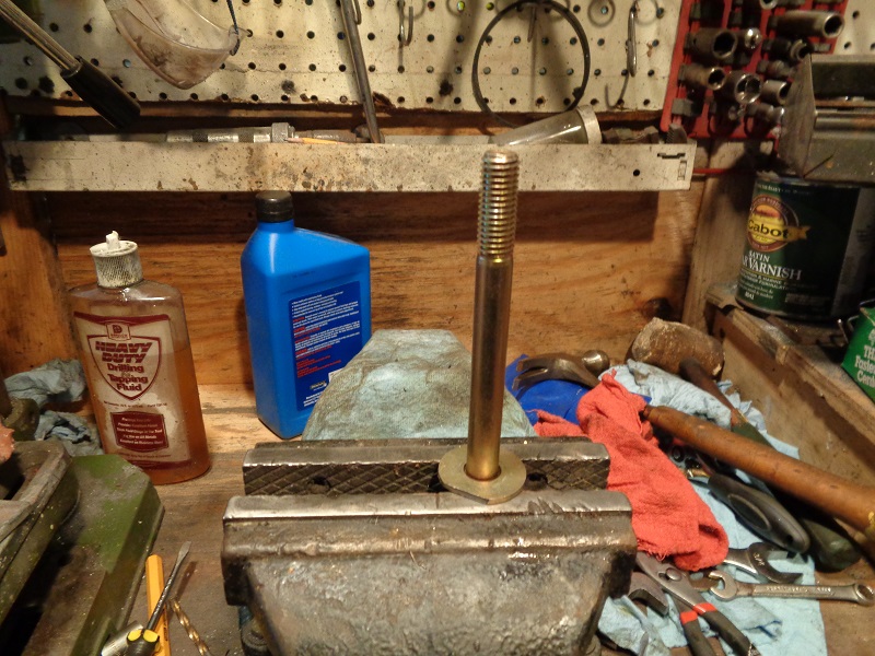
| Standard 1/2“ washers were cut down on one side to clear the rising edges of the arms to get a flat pull on the bushing. Then the bolt hex was stood up into a bench vise. 29) |
||
 |  |  |
| One modified washer, then the rocker installed over the bolt. Adjust the washer to fit around the arm. Then add the bushing, second washer and nut. Make sure the split in the washer is facing up as in the installed position. At this point, it doesn't matter about the position of the notch made in the second washer. |
||
 | 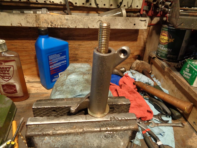 |  |
| Turn the bolt in with the wrench in one hand and the other hand on the rocker (as you would with a torque wrench). This will help keep the turning force centered and keep the rocker arm from moving in the vise. When you've gotten down to the rocker arm with the washer, loosen the nut and reposition it around the arm and snug the nut back down. This will help give an even pull on the bushing when you get that low. |
||
 |  |  |
| When the nut bottoms out, remove it and the washer to check that the bushing is flush with the arm end. If not, you can try the old bushing as a spacer but with it being split, it's a one trick pony then the sides push wider than the new bushing. Test fit the arm into the rocker box to see if it will bind up while installing it. |
||
 |  |  |
| If so, the bushing isn't home yet. The nut below was installed alone to pull the bushing in the rest of the way. The washer apparently bowed in the middle close to the end and wouldn't finish pulling in the bushing. Test fit the arm once more to make sure it will reside in the rocker without binding when turning side to side. | Look for protruding burrs on the end of the bushing. | |
 |  |  |
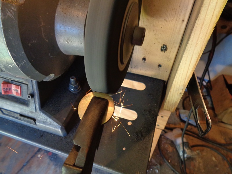
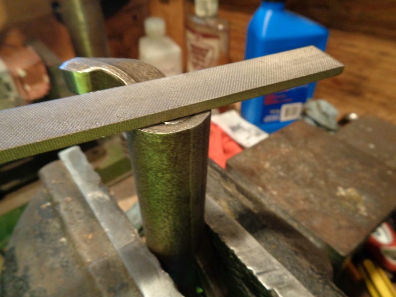
| If needed, the end of the bushing can be filed down flush to the rocker arm. Place a straightedge across the assembly to ensure it's flat end to end. The file will cut down the bushing before harming the hardened rocker arm. 30) |
||
 |  |  |
Ream and Lap the New Bushing
The proper way to ream rocker shaft bushing's is to come in from the opposite bushing with the reamer. 31)
That way the existing bushing acts as a guide for the bushing being reamed.
Factors for a good reaming job include; 32) 33)
- Alignment: The bushing needs to be in perfect alignment when pulled into the rocker arm.
You'll also be using a wider bore (existing used bushing)than the reamer as a base line.
Choose the best bushing of the two to replace last.
The reason for line boring is to get a straight line thru for the shaft.
What is bad about a reamer and going free hand is bell mouth. 34) Slight wiggles can create a wider opening on the outside of the bushing.
Using the existing bushing thru to the new one 'helps' to keep the reamer centered in the rocker arm. - Size: You have little, if any, control over the finished size the reamer gives while doing this at home.
You basically get what the reamer gives. Finished over size or under size is not a good thing.
Sizing needs to be done to fit each rocker shaft to it's corresponding bushing. I.E. A to A, B to B, etc. along with trial fitting with zero burrs or high spots on the shafts. 35) - Position: Each bushing should be installed straight, not cocked or collapsed. 36)
If the new bushing installs at a slight angle, this will throw the position of the reamer off.
Then the reamer will have to cut at the same time it's fighting a non straight path toward the end of the bushing.
The bushing will shrink when it is squeezed into the arm bore.
The slit in the bushing may also distort to an 'out of round' condition when installed creating a bumping condition while reaming. - Surface finish. Again you have little, if any, control over this at home. You basically get what the reamer gives. Too course isn't good for bushing life.
- Machining conventions. This is the method for replacing the bushings in the rocker arm as explained in the FSM.
The process is slow, not to mention the variances in accuracy.
Chances are the MoCo used dedicated machinery to handle this task.
This method is an answer to a field tech or home mechanic needing to change the bushings.
Chances are the results will not be as good as the factory machining hence the wide spec range for a new installed bushing job.
The process;
- Line ream the bushing using rocker arm bushing reamer (94804-57).
- “Jims” also makes this tool. You can find it online.
- Use the remaining old bushing as a pilot hole (to keep center).
Reaming
| Keep plenty of cutting oil or lube on the reamer. 37) |
 |
| A 12 mm socket and wrench can be used to turn the reamer. But a standard tap wrench works good. You can see how much was cut out during reaming. 38) | ||
 |  |  |
| The reamer was sent back through with resistance noticed. But no more shavings ended up on the reamer. So the reamer is done cutting even though the shaft will not slide into the bushing and probably from one or more conditions above. The reamer theoretically cuts a center hole thru / from both bushings. However, the hole now has to be lapped to widen the 'centered' hole to accept the shaft. (in proper clearance) 39) |
||
 |  |  |
| You can see beginning reamer cut in the first pic below. As the reamer came thru, it didn't cut in the middle as well as it did in the beginning. This left an app .0003” hump in the middle of the bushing. Some of that came out with a short lapping with 220 grit. |
||
 |  |  |
| The reamer was lightly ran back through. | This revealed a dark ring where the reamer was binding but not cutting. | |
 |  |  |
| The shaft did slide in with light resistance but repeated turns with the reamer also created heat in this spot. It still needed to be lapped for greater clearance. | ||
 |  |  |
| The high spot was taken out after lapping. |
 |
Line Lapping
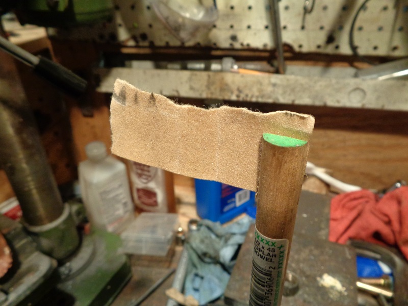
A lapping tool can be made from a 1/2“ wooden dowel and a small piece of sandpaper. 40)
Make the dowel long enough to run the full length of the rocker arm plus enough to get a hand on to turn it (12” or so).
Use a hacksaw blade cut a slot down the middle of one end to hold the sandpaper.
Make the slot longer than the bushing so you can be sure to have contact on the full length of the bushing.
 |  |
Initially cut a piece of sandpaper to go one full revolution around the dowel. 41)
Too many wraps will not slide into the bushing as it will then be too thick.
You can add more if needed but be sure and measure the bore periodically so it doesn't get out of clearance.
You just need to turn or lap the bushing slowly and evenly.
This will also smooth out the bushing surface for a less restriction on the shaft.
Grit of sandpaper will be determined by the condition of the bore and clearance desired.
Insert the bare end of the dowel into the bushing to lap and exit the dowel out the non lapped bushing.
This will allow you to basically line lap the intended bushing to help keep center between the two.
| 60 grit was used first for a couple rounds followed by 220 grit paper (re-measuring before each new piece was used).42) | ||
 |  |  |
| Line lap, measure and check shaft fit and movability. Each time you remove the lapping tool, spin it out while pushing on it. This will help keep from creating an axial scratch in the bushing. 43) |
||
 |  |  |
Repeat until the clearance is correct at each bushing / shaft end (individually measured and matched per side).
| A drill with fine sandpaper can also condition for a slick surface. Test fit with the assembly in the rocker. 44) | |
 |  |
Repeat for the other bushing(s)
- Once you've got the new bushing reamed and lapped, repeat the procedure for the bushing on the other end.
- This time, you'll use the new (sized) bushing as a pilot hole to ream the second bushing.