Table of Contents

EVO: Engine Mechanicals - Sub-04A
Removing the Rocker Boxes
See also in the Sportsterpedia.
First, it is suggested to acquire a Factory Service Manual (FSM) before doing any work on your bike. 1)
Installing or removing the rocker boxes is not complicated. 2)
But, it could very easily be done the wrong way with bad results.
While it is mostly just unbolting parts and bolting them back on, some care should be taken.
Simply unbolting things and throwing them back together can cause harm to engine parts.
Plan Ahead
Mark all valve train components as they are removed so they will be re-installed in there original locations. 3)
Remove one rocker cover / box assembly at a time.
Make Room for Parts
Plan ahead to have a place to store bolts and parts.
This way they won't get mixed up or lost and it'll make reassembly go smoother.
You can use a Ziplock bag or an old piece of cardboard for each set of rocker bolts and parts.
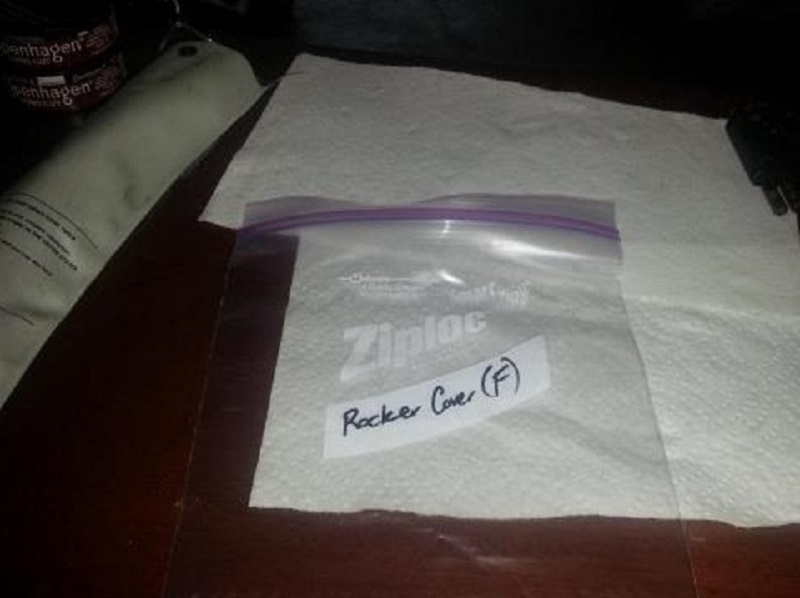 4)
4) 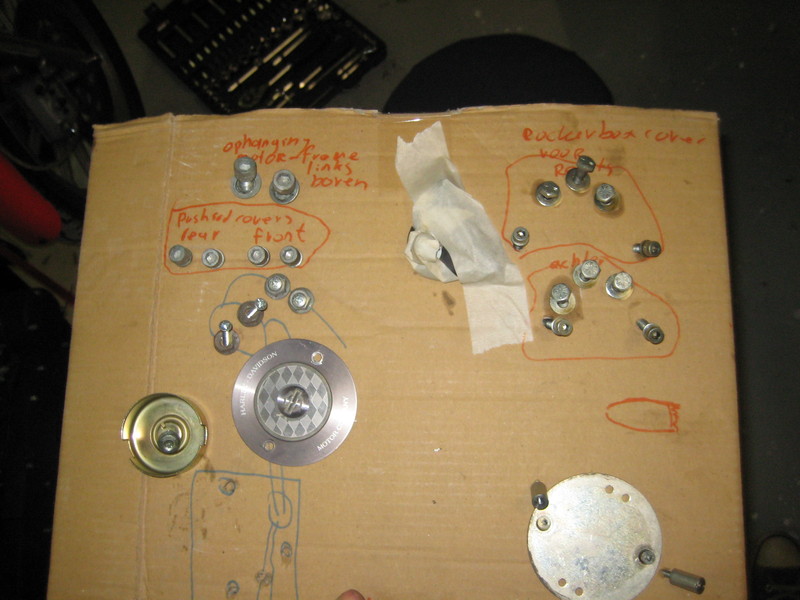 5)
5)
Keeping / Discarding Gaskets
The FSMs say to remove and discard the gaskets and fiber washers.
However, unless they are in bad condition (pinched, torn etc.), they can be reused.
This is a judgment call.
Most gaskets can be easily replaced if you have a leak from re-using the old ones (except the lower cover gasket).
If installing new gaskets, the old ones can be stored for spares if needed. 6)
 |  |  |
Make Room to Work
Disconnect and remove the fuel tank: 7)
The tank will be cumbersome to work around if left on.
Turn the petcock valve off. Remove the fuel line and vacuum line (if applicable) attaching to the petcock.
Remove the fuel vapor line that attaches to the fuel tank. Remove the front and rear tank attachment bolts.
The tank will then pull out from the top.
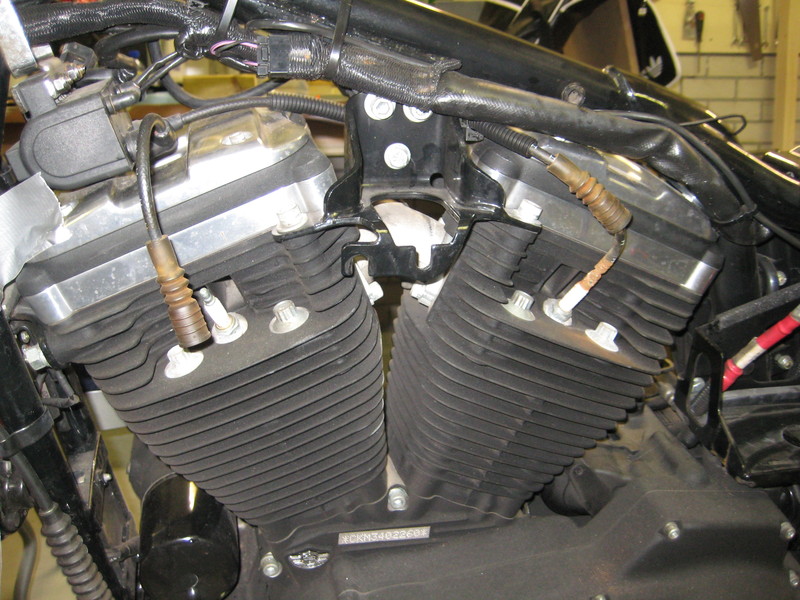
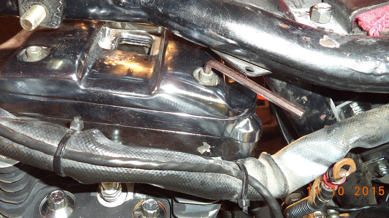
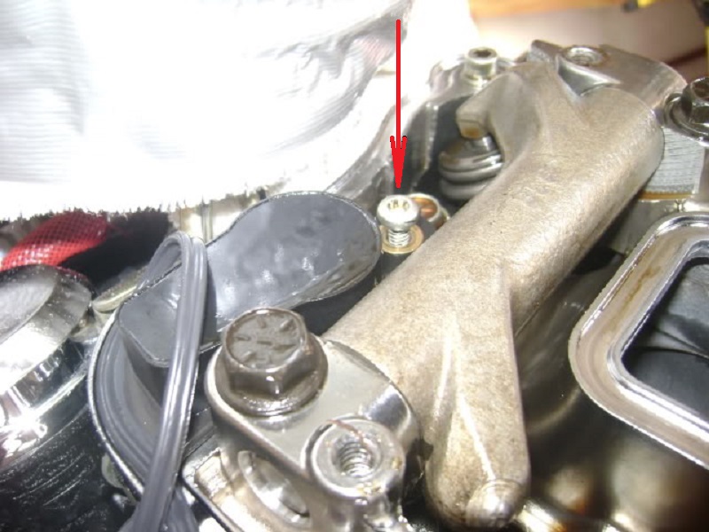
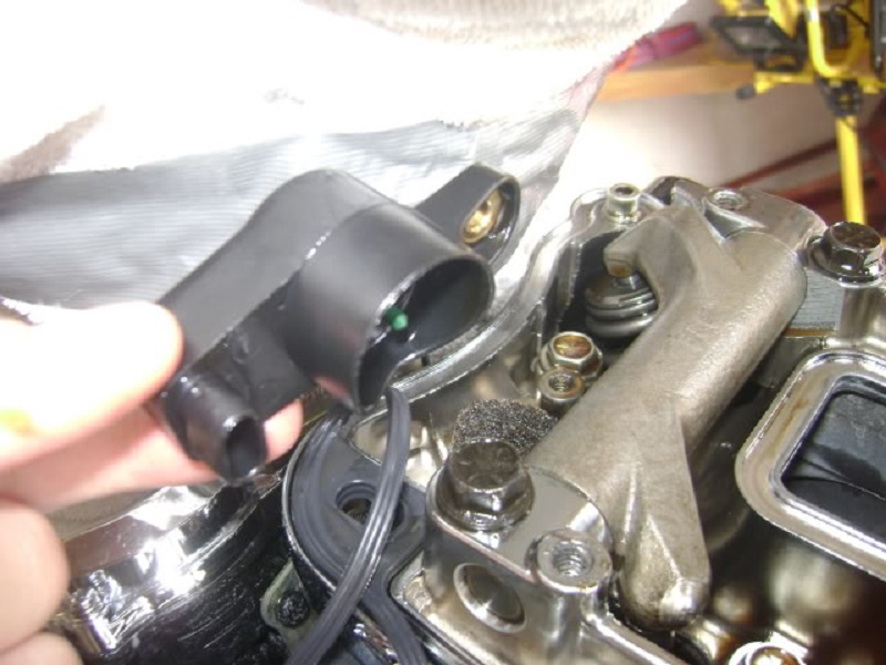
Remove any other items between the frame and the rocker box that may hinder removal of the rocker box (plug wires, VOES, MAP, etc.)
The rest can be left on unless you just want or need to remove them anyway. Tie up any wiring that may be hanging.
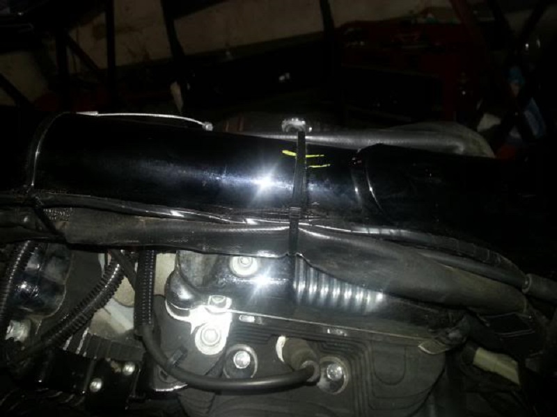
You may also want to cut and remove the wire strap on the main harness over the rear cylinder.
Then you can nudge the harness out of the way for removal of the rear left rocker bolts.
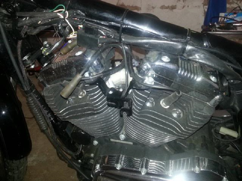
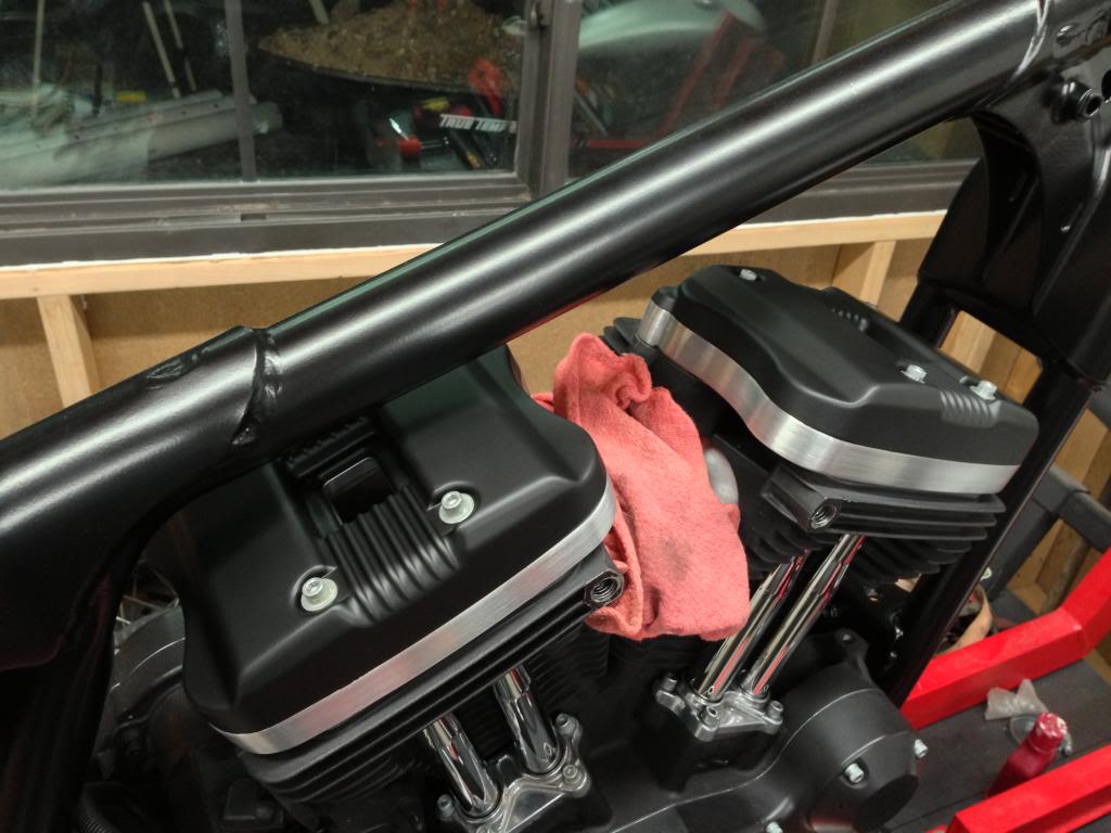
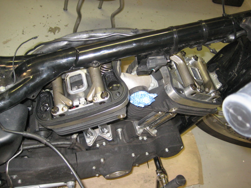
| Fuel tank and other appurtenances removed. 8) | |
 |  |
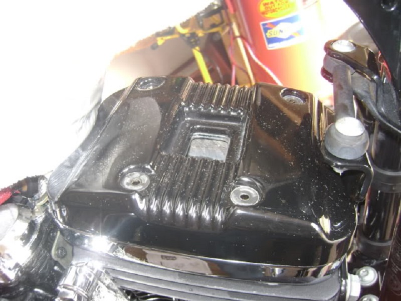
Remove the Upper Cover
86-03 engines have rocker boxes consisting of three pieces;
The outer cover (aka upper cover).
The spacer (aka middle cover).
And the inner cover (aka lower cover).
2004 and up rockers boxes only have two pieces;
The outer cover (aka upper cover).
And the inner cover (aka lower cover).
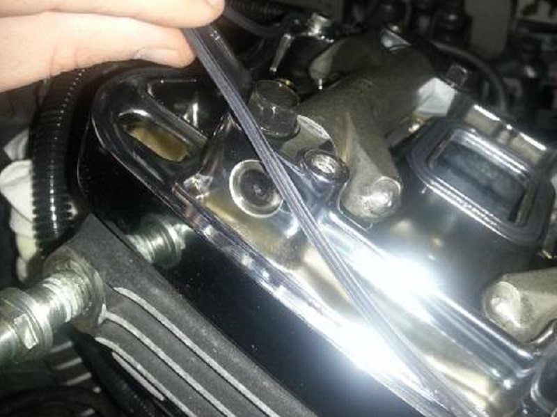
Remove the 4 screws with captive steel washers and fiber washers on the top section.
If installing new fiber washers, the old ones can be stored for spares if needed.
However, new ones are cheap enough to have some on hand as spares when needed also.
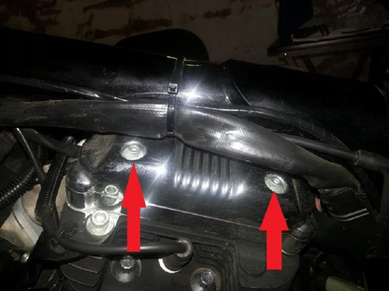
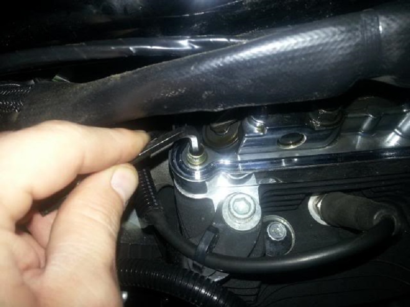
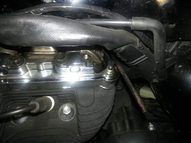
| These two screws can be more difficult to get to with the wiring harness attached to the frame. 11) | Put the screws and washers safely away. 12) |
 | 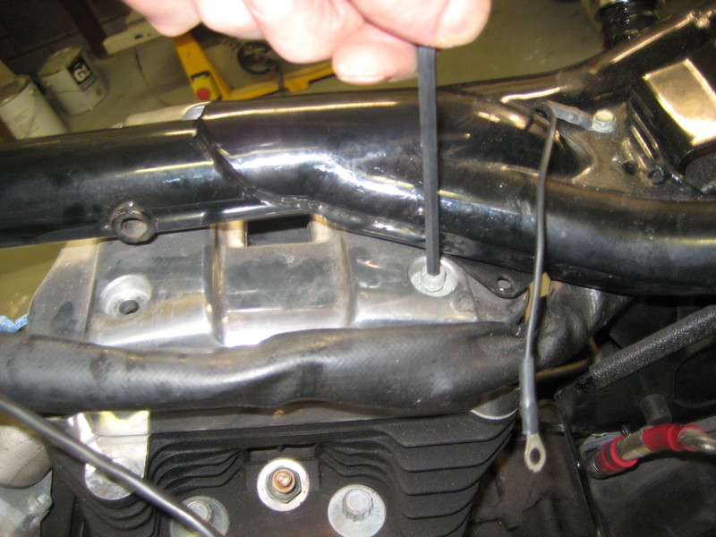 |
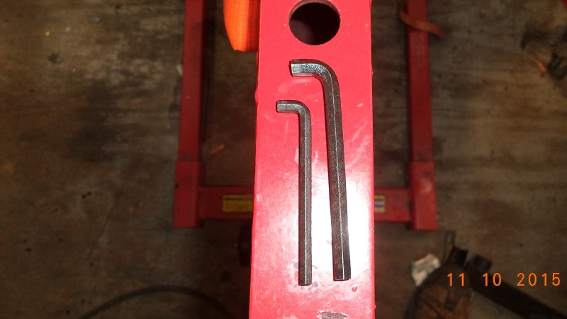
| An Allen wrench end cut shorter with a Dremil cut-off blade works good. 13) | |
 |  |
Then remove the outer cover and put it safely away.
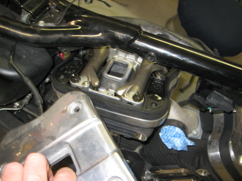
Remove the Middle Cover (86-03)
The middle spacer simply lifts off.
Remove it and place it safely away.
The umbrella valve is installed in this part on 86-03 engines.
These little rubber parts dry out and get brittle over time.
Remove and replace them now so they don't cause you problems later.
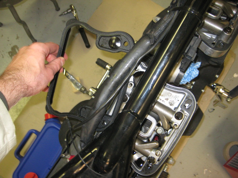
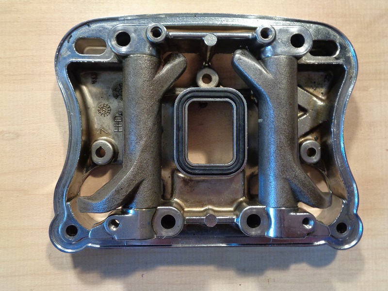
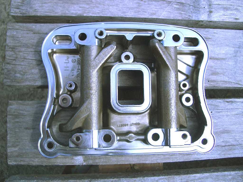
| Middle rocker box spacers on a 95 model 16) | |
 |  |
Before Removing Lower Cover
About Relieving Valve Pressure
See also Hydraulic lifter disassembly - inspection - assembly in the REF section of the Sportsterpedia.
(also known as “Bleeding the Lifters”)
You are not actually doing anything but allowing the oil time to leave the lifter body out of the holes in the each lifter before removing the lower rocker mounting bolts.
Due to viscosity of the oil and hole locations, it usually takes 20-30 minutes.
Internal clearance and parts determine bleed rates. 17)
The 86-03 FSMs state to rotate the crankshaft so both valves are closed on the head being repaired.
Then remove the two 5/16“ rocker arm retaining bolts first and remove the rocker arm shaft.
In theory, you've already relieved the valve spring pressure by rotating the engine over until both valves are closed.
But you haven't relieved lifter preload against the valves which still puts upward pressure on the rocker box.
They also do not state to wait 20-30 minutes before removing the bolts. But if you don't, the bolts will have more pre-load from the lifters.
And that pressure is still on the rocker arms and also the rocker box.
So, removing the two 5/16” bolts first would relieve the lifter pre-load / valve pressure for you.
This removes lifter preload from the valvetrain.
However, with the rocker bolts in place other than these two, that would send the pressure release down to the cam bushings by jolting the camshafts all of a sudden.
This could cause the camshafts to crook sideways and gouge the bushings.
They 04-Up FSMs still state to rotate the crankshaft so both valves are closed on the head being repaired.
But they changed the sequence of removing the bolts.
Removing them in the proper order also prevents potentially warpage of the cover(s). 18)
It also mentions making sure that both valves are closed prior to removal for each cylinder (separately) of the rocker box you're removing.
Lifter Preload:
Lifters have about 2“ of internal travel length (down to up movement).
The pushrod lengths are designed to be in the middle of lifter travel.
This means the pushrods should be compressing the lifter springs down by app. 1” with both valves closed.
This spring load is even more with the lifter pumped up with oil.
Total static lifter spring pressure with both valves closed is a combination of your individual pushrod lengths, amount of oil and initial pre-load in the lifters.
You can't change the length of solid pushrods or the initial lifter preload.
But you can relieve some spring pressure by allowing the oil pressure to bleed down from the lifters before removing the lower rocker arm bolts.
Non compressed lifters also have a small amount of preload by themselves and even being bone dry of oil.
| Photos of a dry lifter. (L) assembled - (R) with spring pressure at rest. On dry assembly, the pushrod cup is relatively easy to push in with you finger to install the retainer clip. If oil was poured into the lifter body and then the cup was compressed, it would be more difficult to push the cup down to install the retainer. 19) |
|
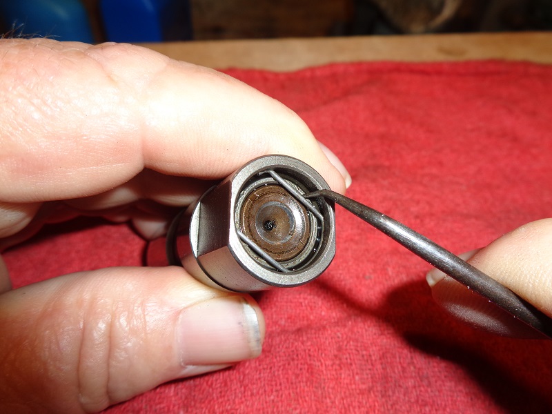 | 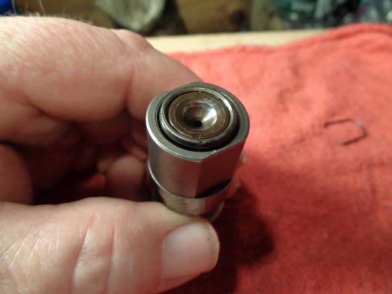 |
Cam lobe positions:
Rocker boxes should really only be removed and installed when the cams are positioned such that the lifters are let all the way down. 20)
Compression TDC is the best place to do this, because it's just about exactly halfway through the valve-closed window.
If you install the rocker boxes at overlap TDC instead, both valves are slightly open. So it's important to be able to tell compression TDC from overlap TDC.
Ten minutes or so is a pretty normal amount of time for lifter bleed down.
It may take longer if it's particularly cold or if you're using heavy oil.
But if you're sitting at overlap TDC, you may never see the valves close because the lifter will shorten as far as it goes and still be too long.
There are two TDC's for EACH cylinder. 21)
The reason there are two TDC's for each is that a 4-stroke motor requires two full revolutions of the crank to complete it's 4 cycles.
Therefore the piston passes through TDC twice;
On one of those TDC's, both valves are closed (compression TDC).
On the other one, both valves are slightly open (overlap TDC).
You want to be at or near compression TDC to remove or install a rocker box.
So it's important you know how to tell the two TDC's apart.
The way you do that is to watch the valvetrain motion as you're turning the engine.
You can't tell by just putting it at TDC and looking at the position of the valvetrain.
When you're at overlap TDC, the valves are barely open, and it will appear they're closed.
So watch the motion of the valvetrain as you rotate the motor forward.
With the rocker boxes removed, that means watching the pushrods.
When you see the intake pushrod moving down, you're on the compression stroke.
Proceed from there to the next TDC and you're at the right place.
It doesn't have to be precise. Both valves are fully closed from about halfway up the compression stroke to about halfway down the following power stroke.
Compression TDC is about halfway between those events, so it's a good reference point, but the window is fairly wide.
Bolt Removal Sequence
It's important to allow the lifters to bleed down.
(prevents destroying the cam bushings)
Also, make sure you can spin the push rods BEFORE removing the lower cover.
Obviously, you can skip these steps and get lucky.
But if you follow the manual, it's easy enough to do correctly.
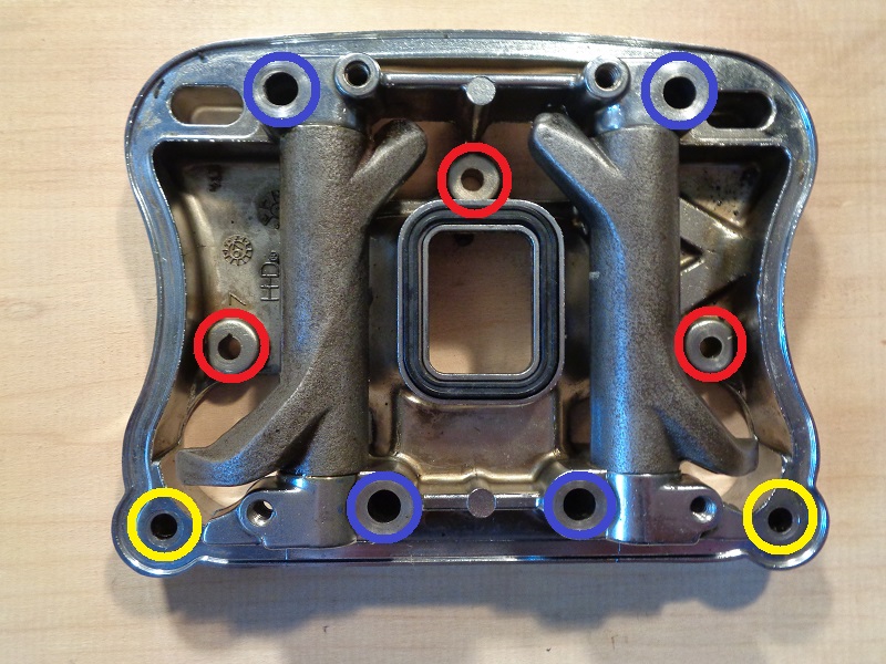
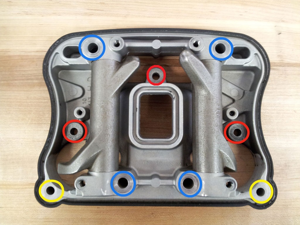
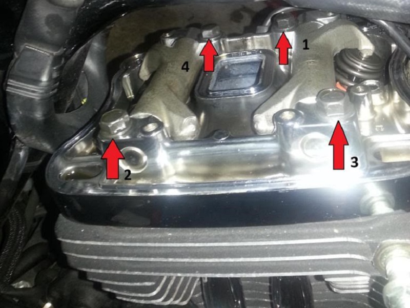
Below is a picture of the respective lower rocker boxes.
The circled areas are where the bolts would be:
On disassembly: 22)
Remove each color set below in slight increments while moving back and forth between them:
- The bolts within the yellow circles.
- Then the bolts within the red circles.
- And lastly the bolts within the blue circles.
- Loosen these slowly with 1/4-1/2 turn increments using a cross pattern 23) to relieve pressure on the lifters evenly.
- An easy way to remember the order is to work on the smaller bolts first and then the larger ones.
To Remove Lower Cover
Remove one rocker box at a time following the entire sequence below.
Rotate the engine until the both valves are closed on either cylinder that you're working on.
This can be done by shifting the transmission in 5th gear and rotating the rear tire forward (with the bike on a lift).
It isn't necessary to bring the engine to TDC (compression) but that would accomplish the same thing.
Both valves need to be closed to relieve the valve spring pressure from the lifters to the rocker arms (thru the pushrods).
See more about Finding TDC (compression) using the rocker arms as a visual in the REF section of the Sportsterpedia.
Before removing the screws, walk away for 20-30 minutes to allow time for the lifters to bleed their oil.
This will also reduce the pressure to the rocker arms.
————— waiting —————
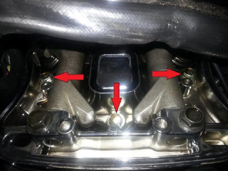
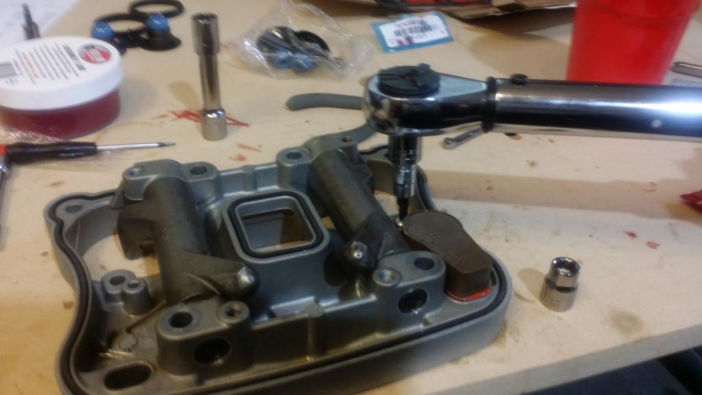
Now, remove the screws holding the inner rocker cover in place in the order described above.
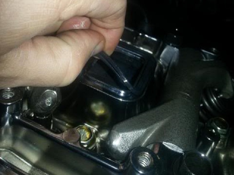
Or for a better visual:
| Loosen these two bolts first. 26) | |
 |  |
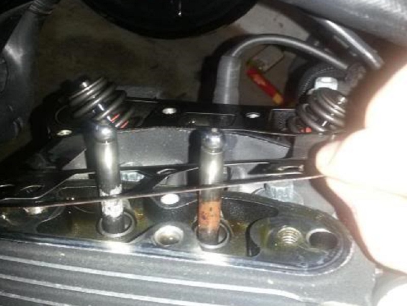
Remove the pushrods from the pushrod tubes:
Mark each one so you can replace them back in the same locations upon installing the rocker boxes.
Each one has it's own wear patterns in the rocker arm cups.
If yours are not painted or labeled, check the lengths. The exhaust pushrods are longer than the intake pushrods. 29)
Mixing intake and exhaust pushrods can result in bent pushrods,damaged valves, pistons and more.
Note: The intake pushrods have an colored painted bands. Newer pushrods may be labeled instead of painted.
But they are still different lengths.
Remove the inner rocker cover as a unit:
The FSM says to remove and discard the gasket under it.
Another judgment call.
However and depending on the condition of the gasket, it may be reused.
If installing a new gasket, the old one can be stored as a spare.
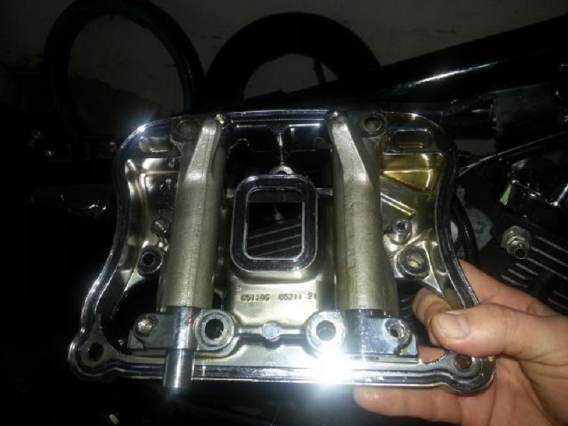
Mark the inner rocker boxes (front or rear) to be installed in the same position on installation.
Valve train components must be reinstalled in their original positions during reassembly. 30)
If not, increased engine wear may result.
The rocker arm tips will be worn into the position of the valve stem travel.
The hole for the breather is also threaded on the correct side for installation.
Remove the Crankcase Breather
86-90
86-90 engines do not have a crankcase breather valve incorporated into the rocker boxes.
91-03
04 and Up
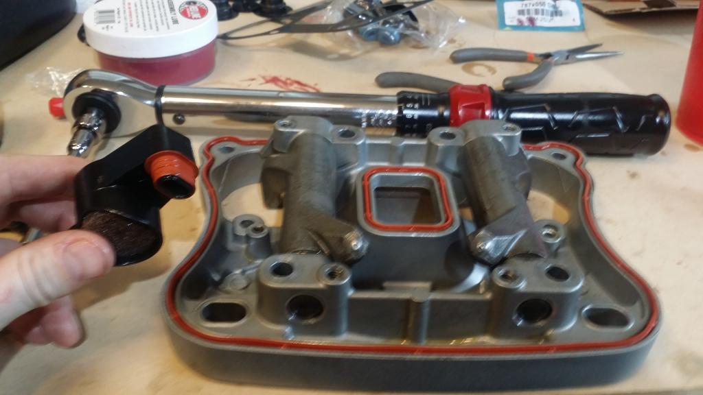
Remove the plastic crankcase breather from the already removed lower rocker cover. It’s attached with 1 screw. 33)
Once the breather is removed, the rubber upper rocker cover gasket can be removed and discarded.
Mark the breather, as it needs to be installed back to it’s original rocker cover.
(The breathers are not interchangeable between front and rear lower rocker covers)
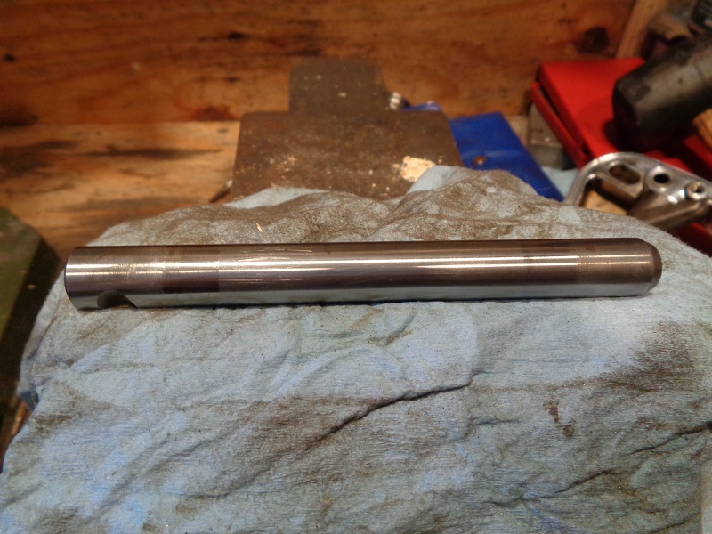
Remove the Rocker Arm Shafts
The rocker arms should be removed, cleaned and inspected for wear and pitting.
The rocker arm bushings should be inspected and the bushing to shaft clearance should be measured.
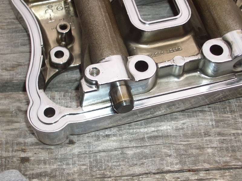
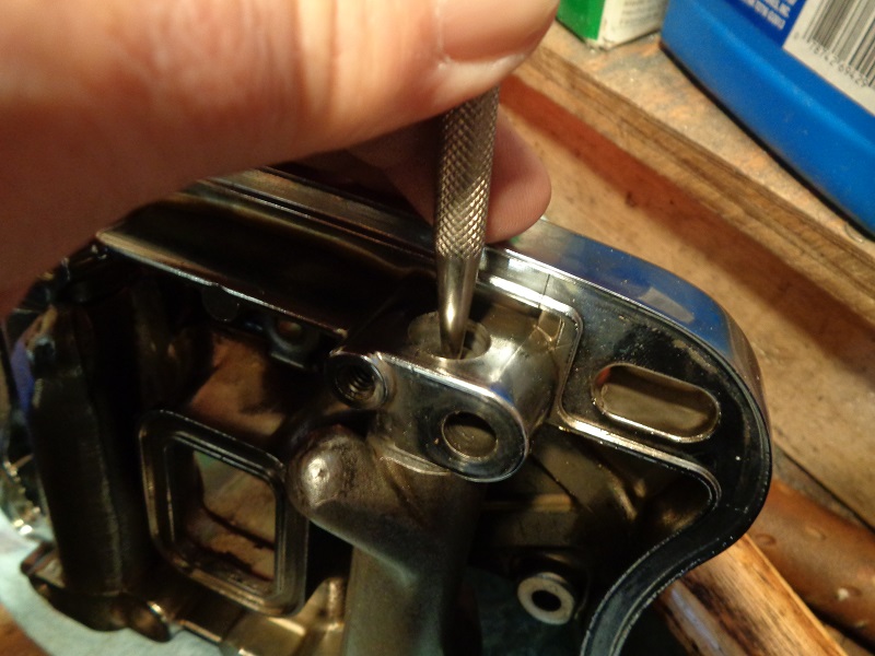
Be careful when handling the inner rocker box (cover) so that the rocker arm shaft does not slide out and hit the floor.
This could result in dings on the shaft and scarred bushings later.
It is held in place by one of the assembly screws and can fall out with the screw removed. 38) 39)
 |  |
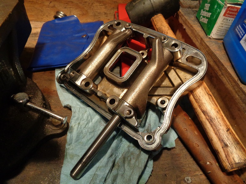
If the rocker arm shafts do not slip out of the inner rocker on their own;
You can remove them for inspection by tapping them out with a rubber hammer and a soft metal punch. 40)
Mark which rocker they came from as well as orientation so they can be reinstalled in their original location.
 |  |  |
Clean All Parts to be Reassembled
Clean all metal parts with brake cleaner or other solvent.
Disassemble and clean the breather valves (04 and up).
Wipe them out and make sure there is no oil globs inside.
Replace the umbrella valves (91 and up).
Even the 04-up breather valve assemblies have an umbrella in each one.
These rubber parts will become brittle over time and will be rendered useless.
It's best to replace them while you have them apart.
Inspect the Rocker Box and Rocker Arms
The rocker box, rocker arms, bushings and shafts should be inspected for wear, pitting and proper clearances per the FSM.
See also Rocker Box / Rocker Arm Inspection and Servicing in the Evo engine mechanicals section of the Sportsterpedia.