Table of Contents
This is an old revision of the document!

EVO: Engine Mechanicals
Timing Inspection Hole
Sub-Documents
Motor Mounts
Click here for Engine Mounts in the Evo Suspension section of the Sportsterpedia.
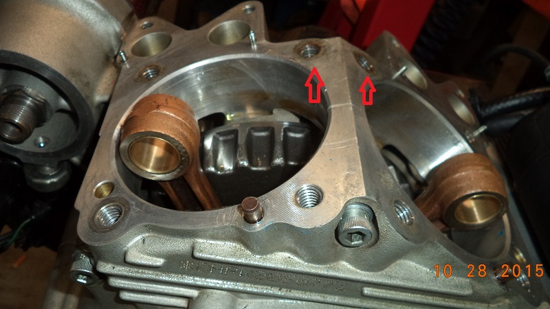
Cylinder Mounting Studs
| Weakest cylinder mounting stud holes in the case. 1) |
 |
Cam / Gearcase Cover
Sub Documents
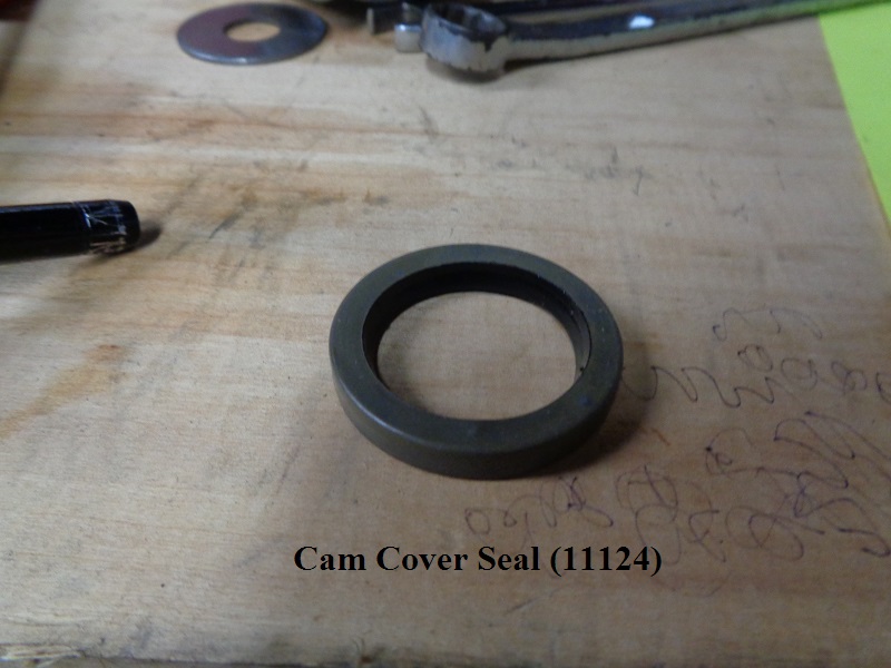
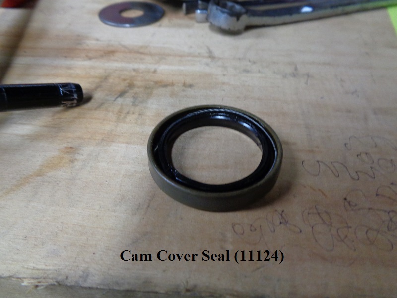
#2 Cam - Cover Seal (86-03)
Seal number (11124):
This surrounds and seals #2 cam when the cover is installed.
See also Removal / Installation of the #2 cam cover seal in the Sportsterpedia.
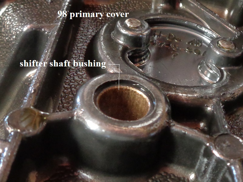
Primary Cover
Sub-Documents
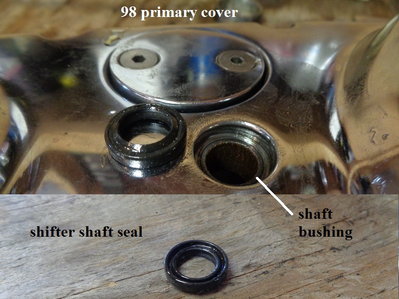
Shifter shaft Seal
This is a shifter shaft seal on a 1998 1200S primary cover.


Engine Case / Sump Drain Plugs
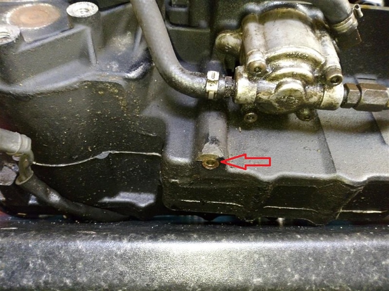 |
| Sump drain on 04 model 4) |
Flywheel Assembly
| Year Model 5) | Flywheel Assembly | Connecting Rod Assembly | Crankpin |
| Early 1986 Models | |||
| E1986 XLH883 | 23905-86 | 24275-86 | 23960-80A |
| E1986 XLH1100 | 23900-86 | 24275-86 | 23960-80A |
| Late 1986-1990 Models | |||
| L1986 XLH883 | 23905-86A | 24275-86A | 23960-80A |
| 1987 XLH883 | 23905-87 | 24275-86A | 23960-80A (std) 23948-87 (.001“ O.S.) 23949-87 (.002” O.S.) |
| 1988 XLH883 | 23905-88 | ||
| 1989-1990 XLH883 | 23905-88A | ||
| L1986 XLH1100 | 23900-86A | 24275-86A | 23960-80A (std) 23948-87 (.001“ O.S.) 23949-87 (.002” O.S.) |
| 1987 XLH1100 | 23900-87 | ||
| 1988 XLH1200 | 23900-88 | 24275-86A | 23960-80A (std) 23948-87 (.001“ O.S.) 23949-87 (.002” O.S.) |
| 1989-1990 XLH1200 | 23900-88A | ||
| 1991-1999 Models | |||
| 1991-1994 XLH883 | 23905-89 | 24275-86A | 23960-80A (std) 23948-87 (.001“ O.S.) 23949-87 (.002” O.S.) |
| 1991-1994 XLH1200 | 23900-90 | 24275-86A | 23960-80A (std) 23948-87 (.001“ O.S.) 23949-87 (.002” O.S.) |
| 1995-1999 All Models | 23905-89A | 24275-86A | 23960-80A (std) 23948-87 (.001“ O.S.) 23949-87 (.002” O.S.) |
| 2000-2003 Models | |||
| 2000-2003 All Models | 23905-00 23905-00A | Not Sold Separate | Not Sold Separate |
| 2004-up Models | |||
| 2004-2005 All Models | 23905-04 | Not Sold Separate | Not Sold Separate |
| 2006-2009 All Models (Except XR1200) | 23905-04A | Not Sold Separate | Not Sold Separate |
| 2010-2019 All Models (Except XR1200/X) | 23905-04B | Not Sold Separate | Not Sold Separate |
| 2009-2013 XR1200 / XR1200X | 23999-08 | Not Sold Separate | Not Sold Separate |
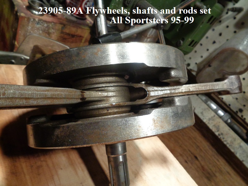
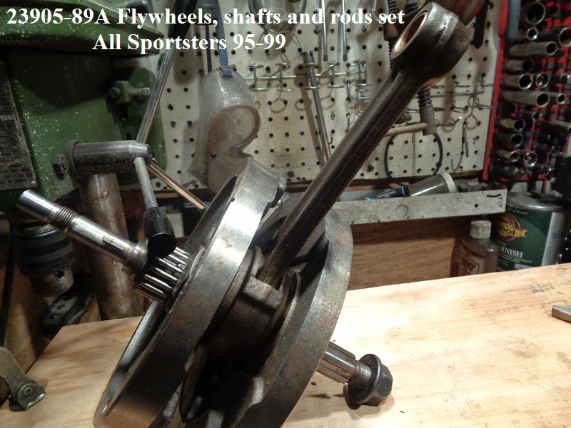
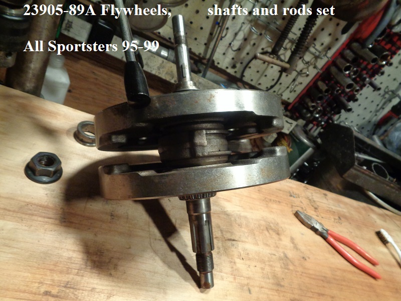
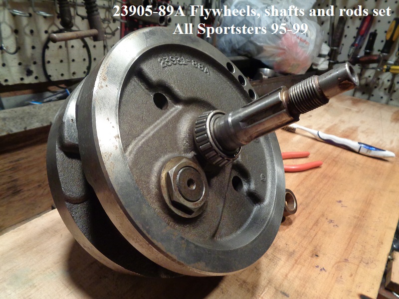
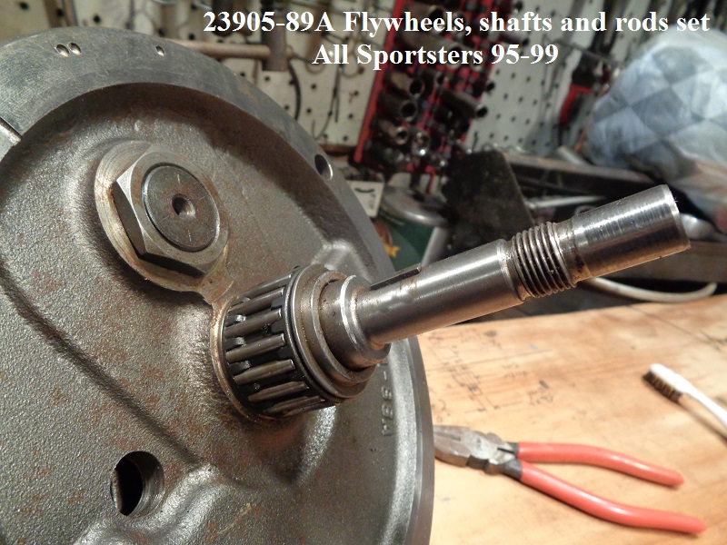
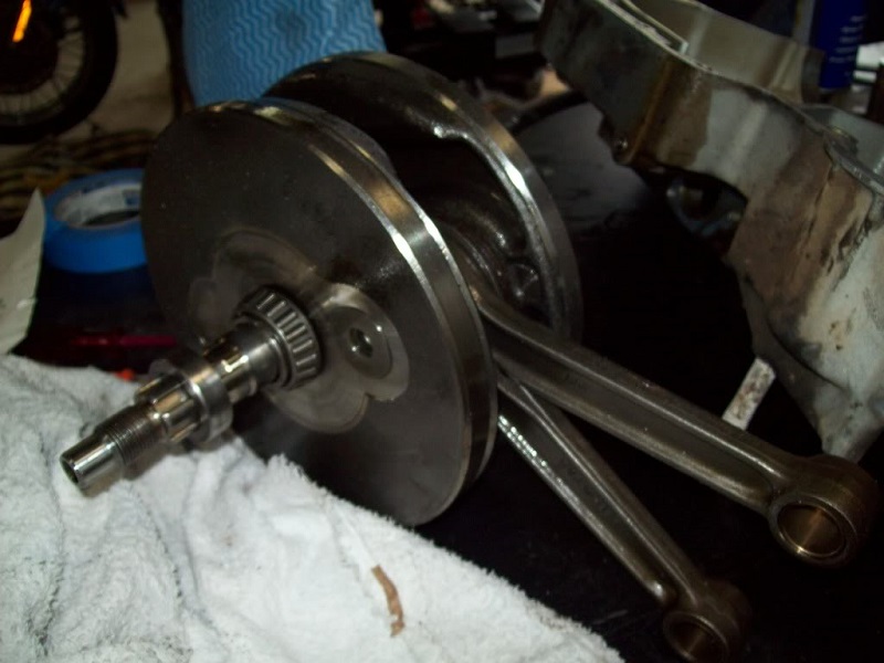
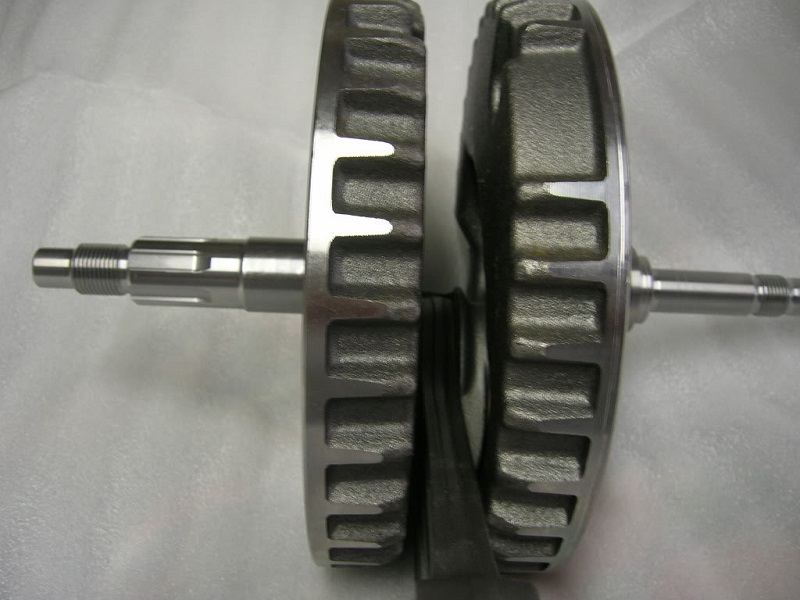
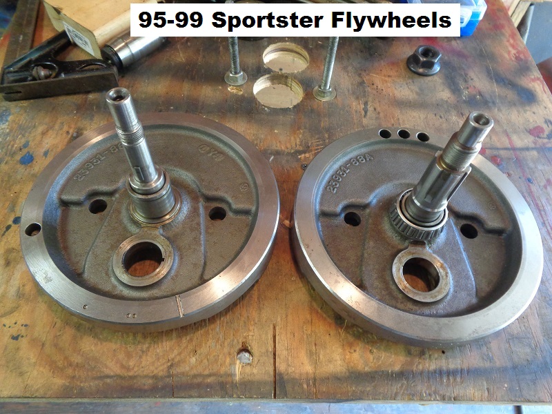
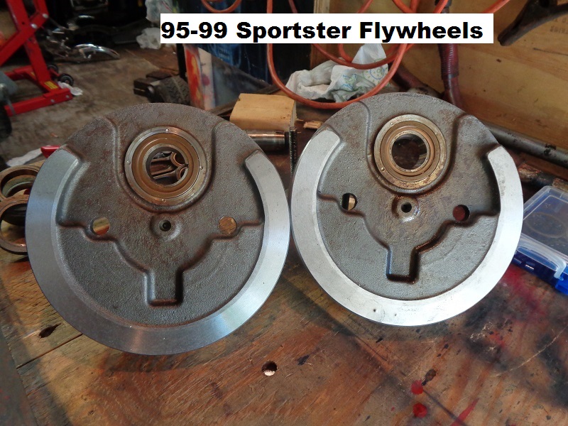
95-99
The same flywheel set was used in all Sportsters 95-99.
Sold as a unit: part number (23905-89A) consists of the flywheels, shafts and rods.
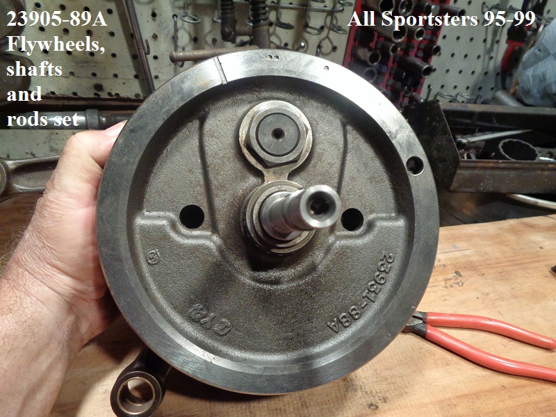
Each flywheel casting number (23931-88A)
Connecting rod set: part number (24275-86A)
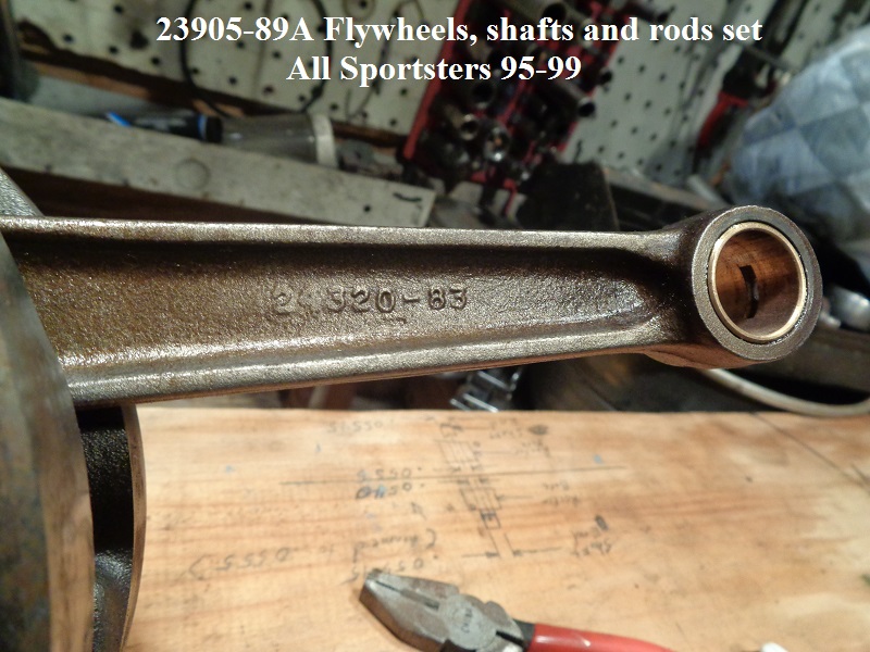
Front connecting rod casting number (24321-83)
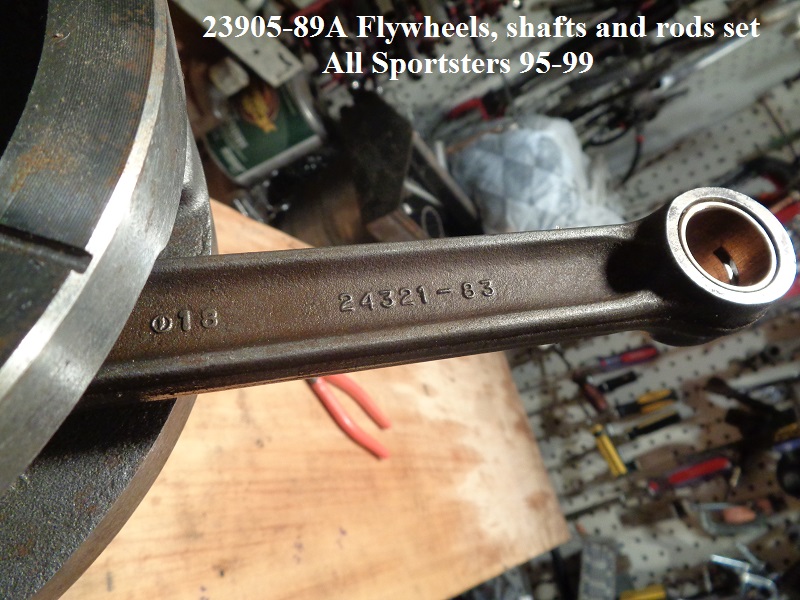
Rear connecting rod casting number (24320-83)
Rod bearing set (24354-87A)
Rod bearing race - front (2)-(24341-52A)
Rod bearing race - rear (2)-(24352-52A)
Piston pin bushing std (2)-(24331-36), .01“ O.S. (24332-36
Crankpin std (23960-80A), .001” O.S. (23948-87), .002“ O.S. (23949-87)
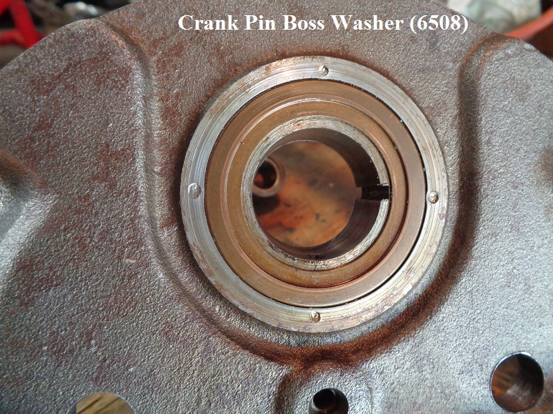
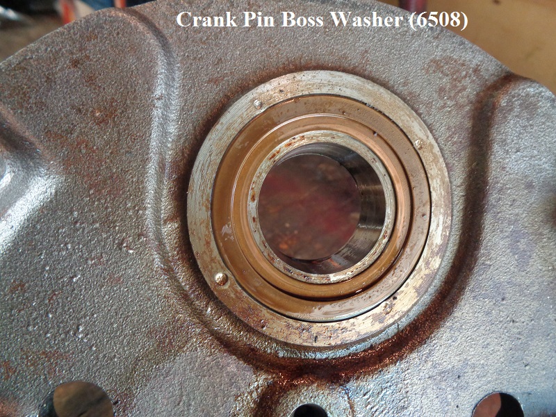
Crankpin boss washer (2)-(6508)
 |  |
 |  |  |
 |  |  |
 |  |  |
00-03
Flywheels
Late 1986 flywheels and crankpin bearing changes.
Information from Technical Service Bulletin #M-927. Click here to see the actual bulletin from this page in the Sportsterpedia.
Beginning with crankcase numbers 883cc (1786 083 003) and 1100cc (1886 090 012), a new (F.A.G.) crank pin bearing set and revised flywheels were installed at the factory.
The new crank pin bearing set (using the existing crankpin P/N) consists of three bearings in a package. Early production engines were assembled without thrust washers.
L1986-later production flywheels had thrust washers staked into a counter-bore in the flywheels. The L86 crank pin bearing set retrofits earlier models.
However, the new bearings require a stepped flywheel thrust washer to provide clearance for the wider bearing cages.
You will select the correct thrust washer for your particular assembly and machine off the raised lip in the area of the flywheel thrust washers' I.D.
This lip must be machined off or you will crush the bearing cage as you assemble and torque the crankpin nuts.
See Tech Tip #14 in the Sportsterpedia for more information.
The L86 XLH883 flywheel assembly is (23905-86A) and the L86 XLH1100 flywheel assembly is (23900-86A).
There were new crank pin bearing clearances also.
The new crank pin bearing set packages were color coded with either a red or a blue identification. This color coding is used by the bearing manufacturer only.
The color coding DOES NOT indicate size selection for crank pin bearing replacement.
1989 flywheel changes.
Information from Technical Service Bulletin #M-971. Click here to see the actual bulletin from this page in the Sportsterpedia.
Beginning June 1, 1988, flywheels forged from a micro-alloyed steel went into production. Part numbers and color codes of assemblies with the new material were changed.
1991-1994 Flywheels.
From '91 to '94 the Crankshaft/Flywheel was balanced according to the engine size, either for 883 pistons or 1200 pistons. From 1995-later, the flywheels are balanced to be between the weight of the 883 & 1200 pistons. 8) This is one reason why riders would use Wiseco pistons in early (pre-2004) 883 to 1200 conversions - the Wiseco 1200 piston & pin was closer to the weight of the 883 combination rather than the stock 1200 piston & pin from HD.
1995-1999 Flywheels.
Flywheel assembly part number (23905-89A).
Each flywheel casting number (23931-88A).
| 95-99 Flywheels 9) | |
 |  |
| L1986-up crank pin boss washer (6508) 10) | |
 |  |
Crank Pin
Crank pin (23960-80A) used from L81-03.
| L87-03 crank pin 11) | ||
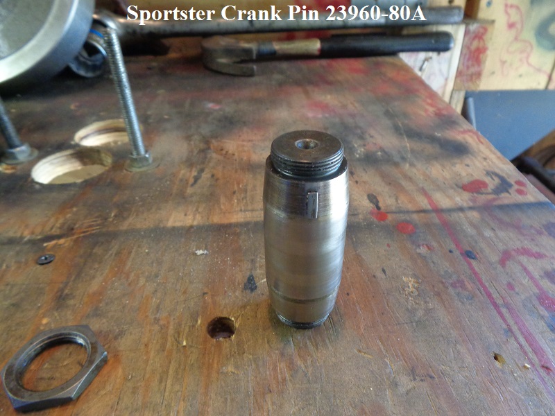 | 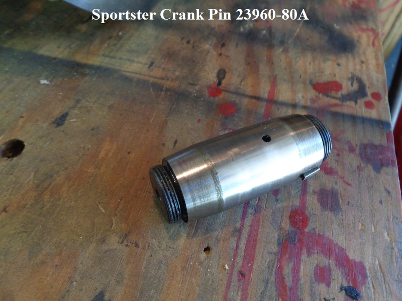 | 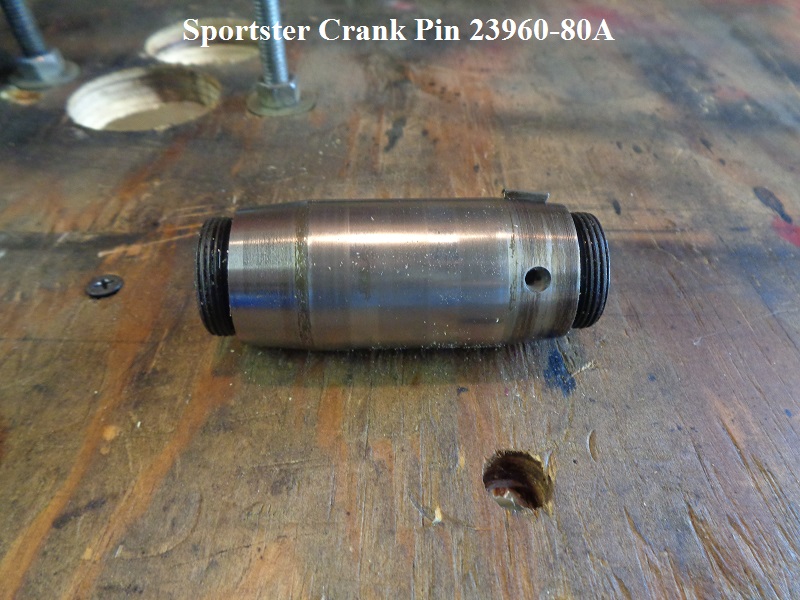 |
2004-Later:
The sprocket shaft nut torque for 2004 & later Sportsters and 2003 & later Buell XB models has been changed. 12)
The torque has been increased from 190-210 ft-lbs. to 240-260ft-lbs.
Remember to clean the threads and generously apply LOCTITE Threadlocker 262 (red) onto the threads of engine sprocket shaft and use a sprocket locking tool.
Some examples of sprocket locking tools are here in the tools section of the Sportsterpedia.
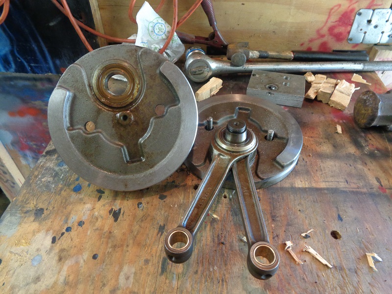
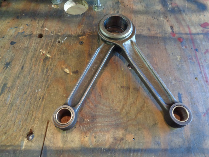
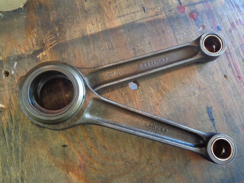
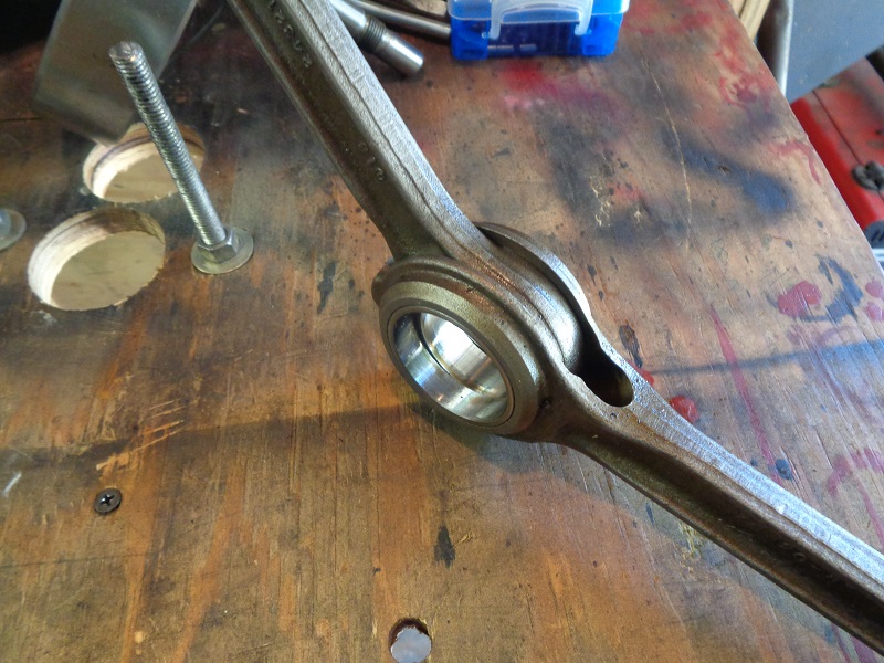
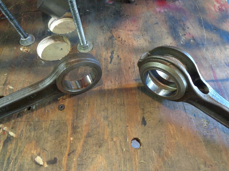
Connecting Rods
Rod set (24275-86A) includes bearings, crankpin and nuts.
Below are pics of just the rods off a 1998 1200S model.
The part numbers cast into the rods are front (24321-83) and rear (24320-83).
 |  |  |
 |  |  |
Pinion Shaft
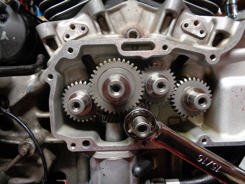
Removing / installing the pinion shaft nut
To remove or install the pinion gear nut,
You'll need to lock the pinion gear from moving while turning it.
It's very important to hold the crank on the pinion side with an appropriate pinion locking tool whenever you take the pinion nut off or put it on.
If you hold the crank still from the primary side (or by putting the bike in gear and holding the brake),
The twisting torque applied to the pinion nut gets transmitted through the crank, from one side to the other.
The crank pin is not designed to resist much twisting force.
You'll risk scissoring the crankshaft (knocking the crank out of true), which requires a full tear-down to fix. 13)
So this is one of those situations where it's best to use the proper tool. 14)
The pinion nut takes a 15/16” wrench size.
90 and Prior Models (4 Speed)
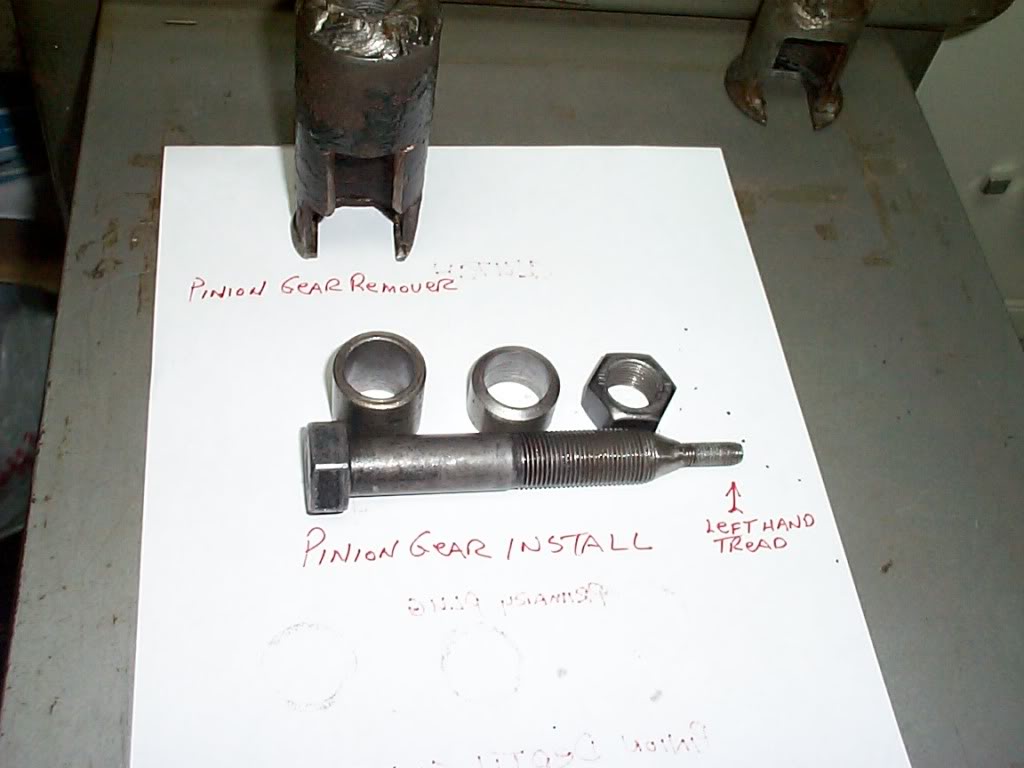 | 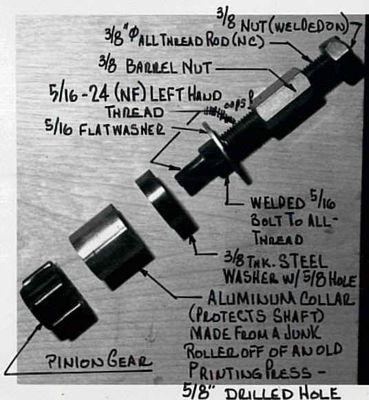 | 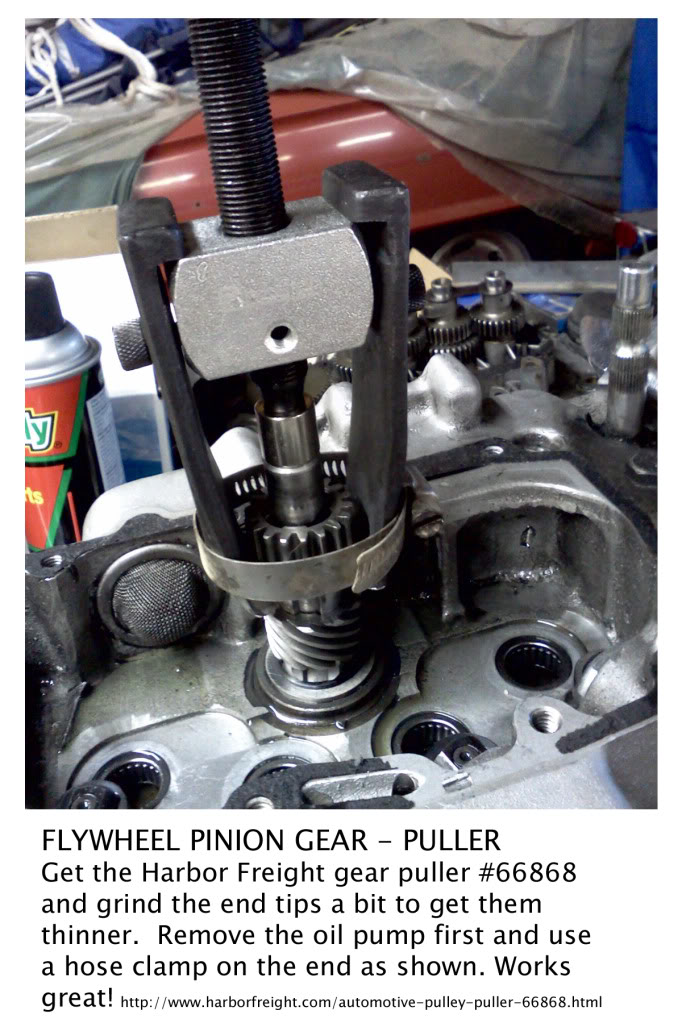 |
| Homemade Pinion Gear / Removal / Installation Tools 15) | Homemade pinion gear press 16) | Pinion Gear Puller 17) |
|---|
 | 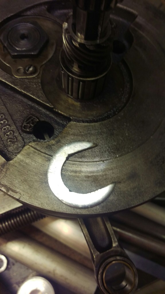 |  |
| Large fender washer cut into a “C” shape and a gear puller | ||
| Homemade Pinion Gear Puller 18) | ||
 |
| 3/8“ stainless steel plate with 20° spokes (for 18 teeth), sawed initial groove to depth and widened it with files |
| Homemade pinion gear locking tool for '89 models 19) |
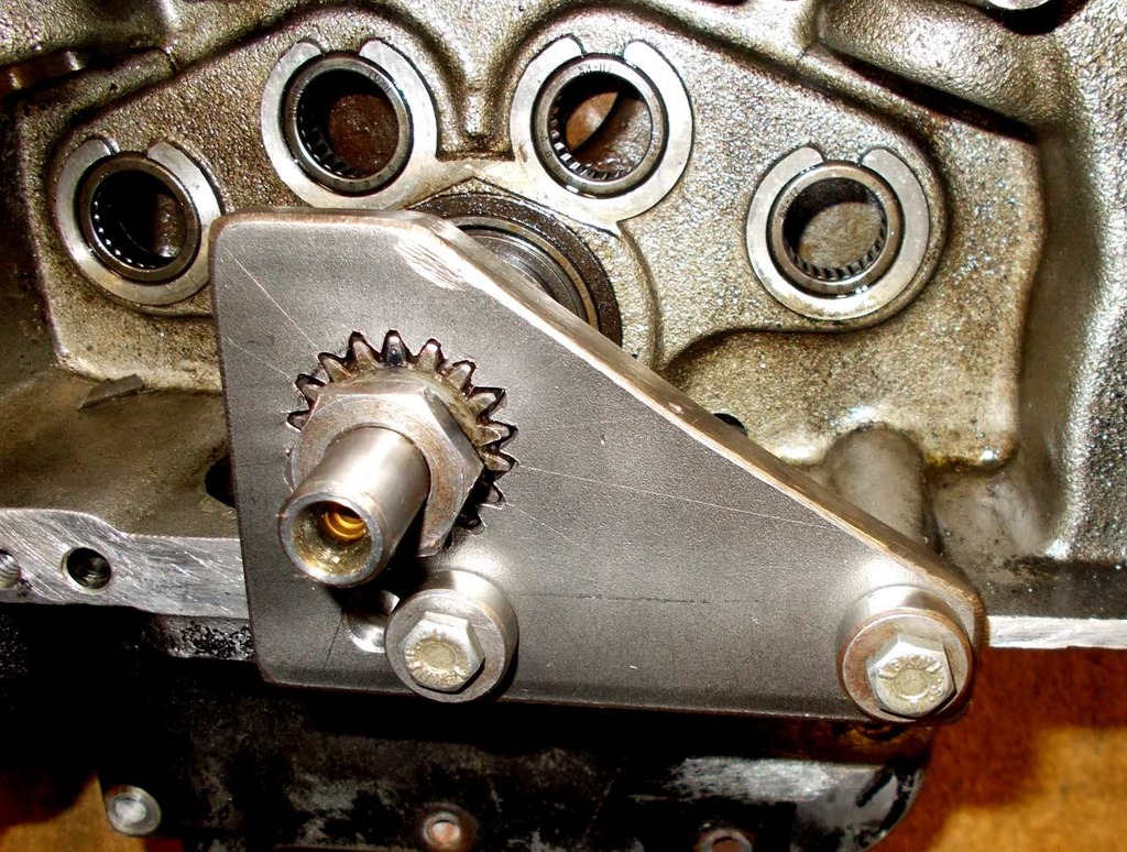
91 and Up Models (5 Speed)
See also in the Sportsterpedia:
Oil Pump Drive Gear
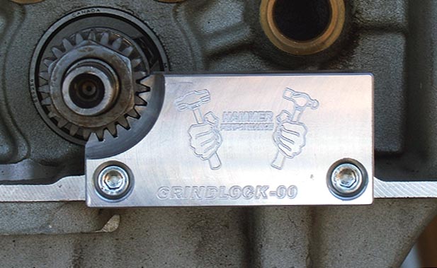
Origin of the Grindlock Tool
- You can use a 15/16” wrench or deep well socket to remove / install the pinion gear nut.
- The Grindlock Pinion Shaft Locking Tool engages for the full depth of the pinion gear for max. strength.
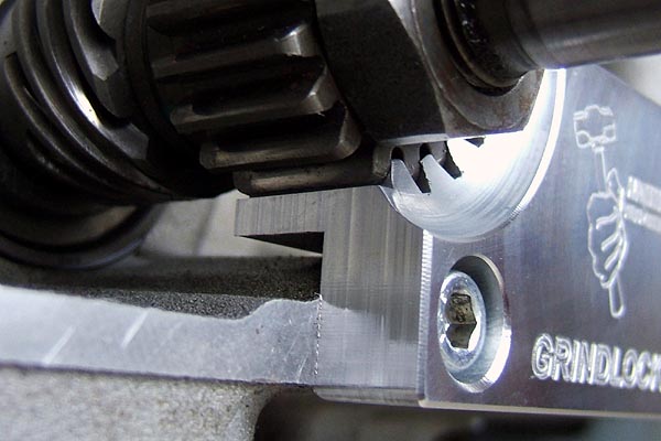
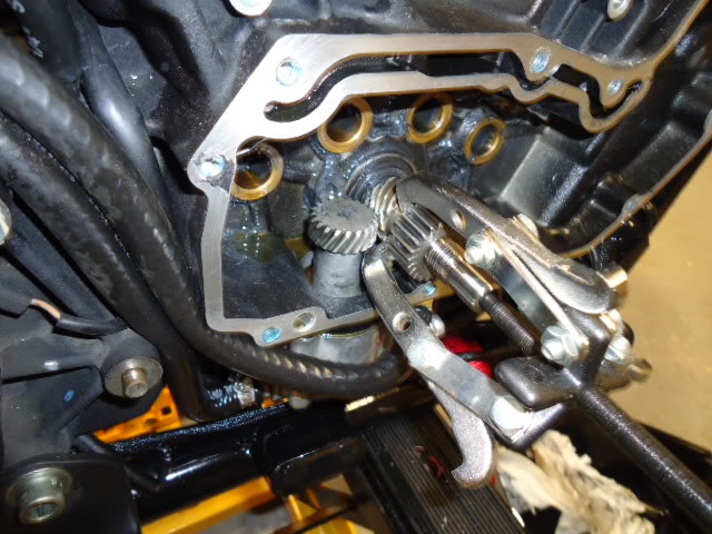
- Once the pinion shaft nut is removed, the pinion gear may or may not slide off by itself.
You can use a gear puller to remove it if it is stuck on.
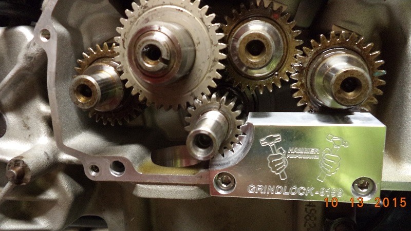
- It's very important to hold the crank still from the cam side (not the primary side) when torquing the pinion nut. 27)
If you for example put the bike in gear and hold the rear brake and torque on the nut, you run the very real risk of knocking the crank out of true.
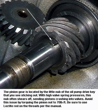
It's not designed to transmit torque from one side to the other and it tries to twist the crankpin connection. - In respect to the key shearing, it's a very common issue particularly when heavy valve springs are used.
However, it shouldn't be the one thing that keeps the gear from spinning. The clamp load should do that.
The caption in the second pic below describes the fix:
Loctite red and 70ft-lbs instead of the factory specified 50ft-lbs. You won't have this issue again.
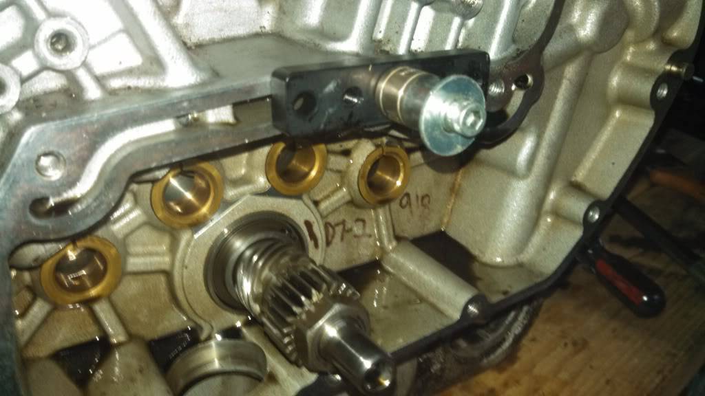
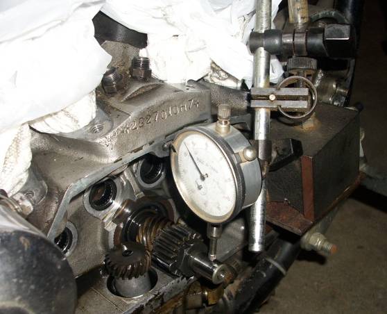
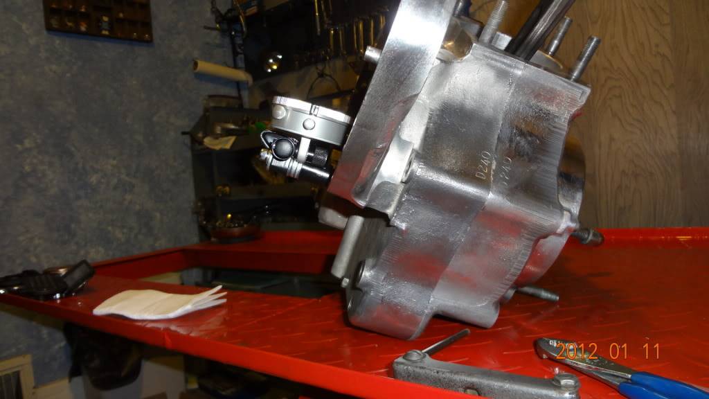
Pinion Shaft Runout
| Attach a scrap piece of metal to the outside of the gearcase and position a gauge holder on it so it won't move while turning over the engine. 30) | ||
 | 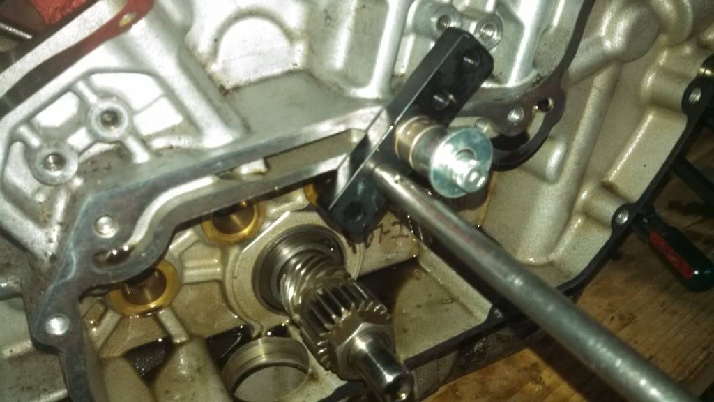 | 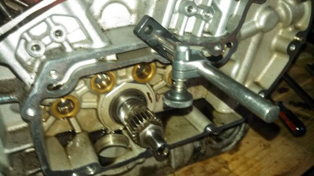 |
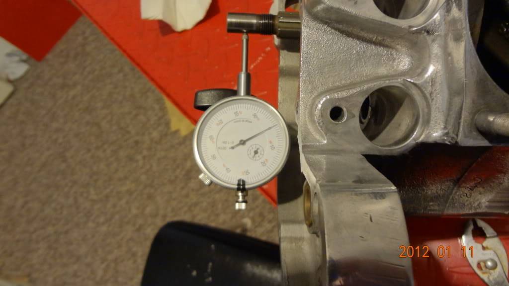
| Install a dial gauge on the holder with the pointer on the pinion shaft. Find the lowest spot while turning the engine over and 'zero' the indicator. 31) | This setup is made with a piece of angle iron for the magnetic base to stand on 32) | |
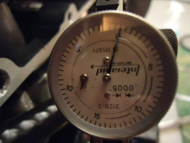 | 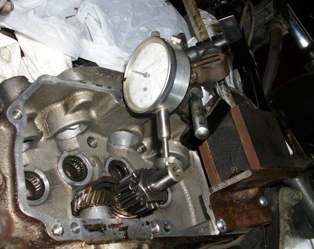 |  |
| This gauge post is threaded into a cover mount hole. 33) | |
 |  |
Crankshaft Seal
Here is a trick to hold the spring in place to stop it popping off while you are fitting the seal. 34)
Before fitting it, pack some grease around the spring in the seal groove. You only need a small amount.