Table of Contents

EVO: Engine Mechanicals
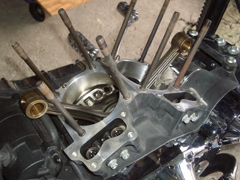
The Camshafts (4 of them) are used to operate the intake and exhaust valves by means of the lifters (AKA: tappets), the pushrods and the rocker arms. The #2 Cam is driven by the Pinion Gear. The Pinion Gear is mounted on the Pinion Shaft which is part of the Flywheel Assembly.
#1 Cam - Rotates CW – Operates Rear Exhaust Valve
#2 Cam - Rotates CCW - Operates Rear Intake Valve - Driven by Pinion Gear
#3 Cam - Rotates CW – Operates Front Intake Valve
#4 Cam - Rotates CCW - Operates Front Exhaust Valve
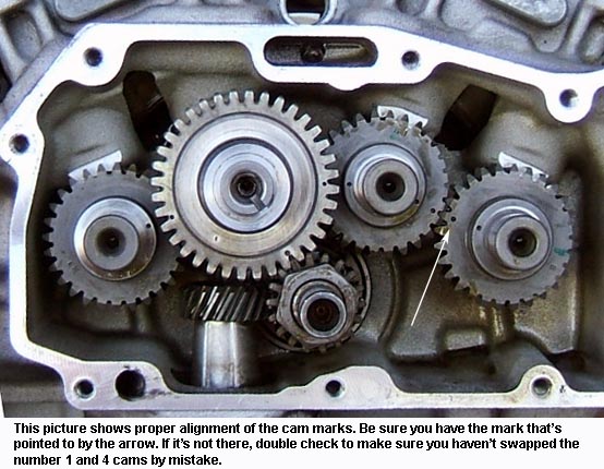
Camshafts
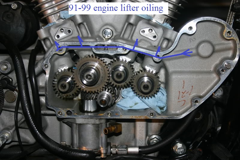
The cams get oiled by drainage from the rocker boxes and splash oil in the bottom end.
Oil flows off the pushrod side of the rocker boxes through the pushrod covers, into vertical holes in the lifter bores and into the gearcase.
Oil falls on the cam lobes on the way down this hole. Some of this oil is transferred between the gear teeth.
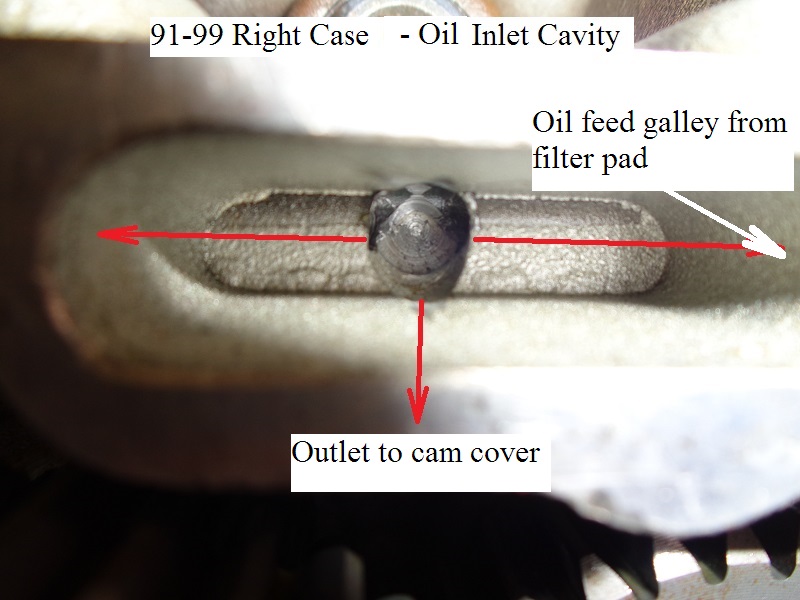
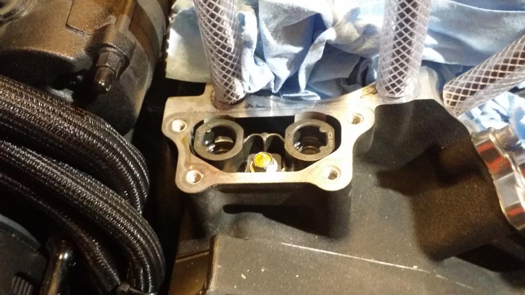
The rear intake (#2) cam gets a little oil spray from the right case oil feed galley through the small orifice underneath the open cavity in the case.
That oil is transferred between the teeth of the cams.
Oil flung off the cams lands in the gearcase to be collected into the scavenge (return) side of the oil pump.
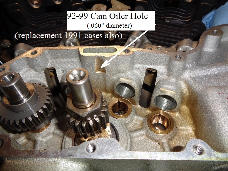
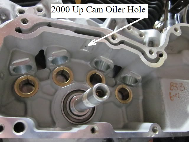
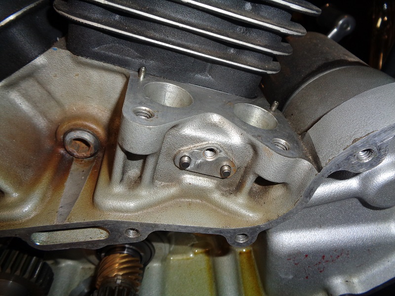
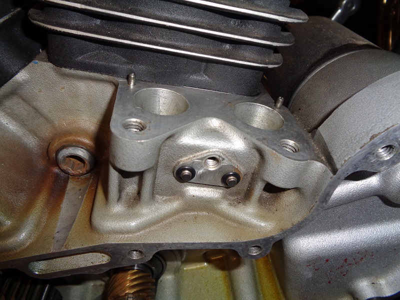
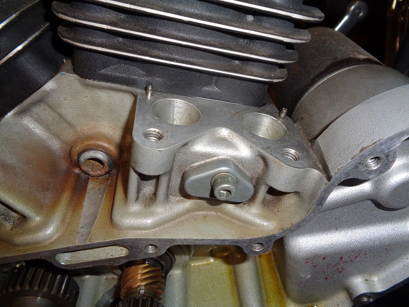
1992-up Cam Gear Oiler Hole in the Right Case.
Below are pics of the restricted orifice underneath the oil feed galley in the case that shoots a small stream onto #2 cam.
#2 cam rotates counterclockwise and the oil is sprayed on the right side of the cam gear for extra cooling (transferred to all cams).
Cam Specs - OEM & SE

- 86-87 “T” cams will not work on 88 and up engines.
- 88-90 “C” cams will retrofit to 86-87
Comparing OEM and Andrews Cam Grinds
These figures are from the Sportster Evolution Cams PDF from Andrews Products. 5)
 |
|||||||
|---|---|---|---|---|---|---|---|
| Grind | I/E | Timing @ .053“ Lift | CL | Duration @ .053” Lift | Durarion @ .020“ Lift | Max Lift | TDC Lift |
| W | I | 10°/28° | 99° | 218° | 256° | .474” | .122“ |
| E | 38°/16° | 101° | 234° | 272° | .474” | .138“ | |
| N4 | I | 30°/46° | 98° | 256° | 296° | .490” | .216“ |
| E | 52°/24° | 104° | 256° | 296° | .490” | .189“ | |
I/E = Intake/Exhaust — CL = Centerline
Thanks to Maxeffort of the XLForum for the following Flywheel Degree Charts of these various cams.6)
The measurements are based on the .053 lift specs. Also, take note that the predominance of the intake valve opening occurs on one rotation of the flywheel and the predominance of the exhaust valve opening occurs on the next rotation of the flywheel. It takes two full rotations (720°) of the flywheel to complete the four-cycle process. (This view of the flywheel would be from the right side of the engine.)


Removing / Installing Evo Cams
Sub Documents
EVO Cam and Pinion Gear Sets
- 86-99 - Matched cam gear set includes pinion gear and gearcase cover.
- Cam gears are individually matched to each specific gear cover using computer modeling in a controlled environment. 7)
- Cams are colored coded with a colored dot.
- Factory gearcase covers were also color coded on the inside with a color dot at each pinion and cam gear location.
- This allowed for separate colored gears to be factory assembled (and later replaced) using gears optimized for the lowest gear whine and rattle.
The dealer had to match the cover and gear colors for replacement covers.
- For 2000-03 the options were:
- Select full matched cam gear sets w/ pinion gear,
- or choose only #2 cam w/ pinion gear,
- or choose only the pinion gear,
- or choose the gearcase cover (now sold separately).
- For 2004-later, the options were:
- Select full matched cam gear sets w/ pinion gear,
- or choose only the pinion gear,
- or choose the gearcase cover (sold separately).
 |
||||||||
|---|---|---|---|---|---|---|---|---|
| Year | Models & Included Parts | Cam Grind ID Letter | Cam #1 | Cam #2 Outer Big Gear | Cam #2 Inner Small Gear | Cam #3 | Cam #4 | Pinion Gear (Drives Cam #2) |
| 86-87 8) | (25488-86) All cams, pinion gear and cover | T | 28T | 36T | 28T | 28T | 28T | 18T |
| 88-90 9) | (25488-88) All cams, pinion gear and cover | C | ||||||
| 91-94 10) | (25488-89) All cams, pinion gear and cover | D | ||||||
| 95-97 11) | (25488-89A) All except '96 & '97 1200C cams, pinion gear and cover | D | ||||||
| 96-97 12) | (25483-96) 1200C cams, pinion gear and chrome cover | D | ||||||
| 98-99 13) | (25448-89B) Std/Hug/1200 cams, pinion gear and polished cover | D | ||||||
| (25483-96A) 1200C cams, pinion gear and chrome cover | D | |||||||
| (25491-98) 1200S cams, pinion gear and silver cover | W | |||||||
| 00 14) | (25193-00) all except 1200S cams and pinion gear (no cover) | D | 28T | 46T | 28T | 28T | 28T | 23T |
| (25190-00) all except 1200S Only #2 cam and pinion gear | D | |||||||
| (25194-00) 1200S cams and pinion gear (no cover) | W | |||||||
| (25191-00) 1200S Only #2 cam and pinion gear | W | |||||||
| 01-03 15) | (25193-00A) all except 1200S cams and pinion gear | D | 35T | 46T | 35T | 35T | 35T | 23T |
| (25194-00A) 1200S cams and pinion gear | W | |||||||
| 04-06 16) | (25193-00B) 883/883C cams and pinion gear | D | ||||||
| (25194-00B) 1200C/1200R cams and pinion gear | W | |||||||
| 07-17 17) | (25194-06) all except XR1200/XR1200X cams and pinion gear | W | ||||||
| 09-12 18) | (25271-08) XR1200/XR1200X cams and pinion gear | ? | ||||||
Cam Gear Changes
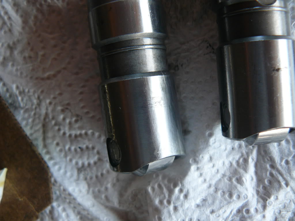
- The #2 “W” cam may or may not have a provision for a timing cup after 03. 19)
- If you intend on installing 04-up “W” cams in 03 and prior engines, look at the end of the #2 cam.
- If it does have a provision for a timing cup, they'll work for prior year applications.
- But, you'll have to either update your pinion gear, or use a press to swap your #2 cam's drive gear.
- For 03 and prior year engines, it needs a drilled and tapped hole in the middle of it and the timing cup notch.
- Below (L), you can see the notch on the cam on the right very easily.
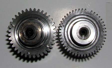
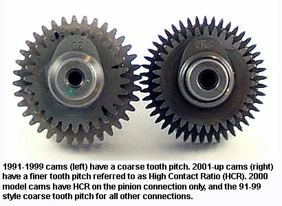
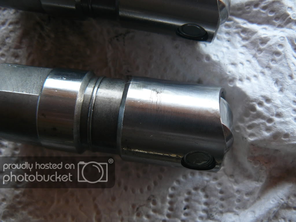
- The #2 cam gear changed from '99 to '00 and again in '01.
- The '99 version has coarse teeth on both driven & drive gears.
- The '00 has a high contact (HCR) driven gear with a coarse tooth drive gears (along with the other cam gears). The pinion gear has HCR teeth as well.
- For 2001, the #2 cam gear has both the driven gear & the drive gear using the HCR type teeth (as do the other cam gears).
- Below (Right Pic), compares the '99 #2 cam gear (left-side) and the '01 style #2 cam gear (right-side).
Cam Bushings
Inner Bushings
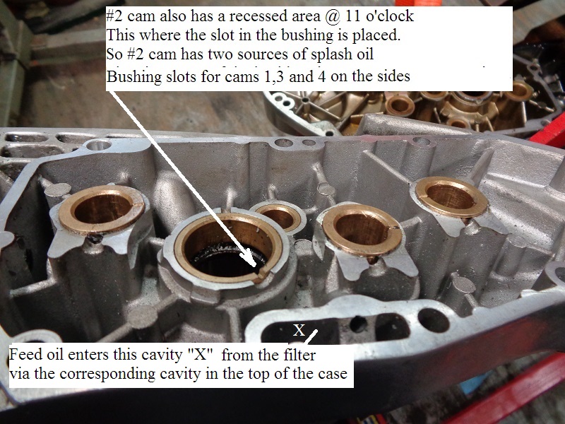
- These bushings get their oil from the fling off of the cam gears and drain back from the top end down the pushrod tubes that puddles in at depressions in the castings where the cam bushing slots are aligned. So basically they are drip fed. Also the cam bushings on the case side are open to the crank behind them, and probably get splash there too. 22)
- Worn bushings can cause excess backlash. 23)

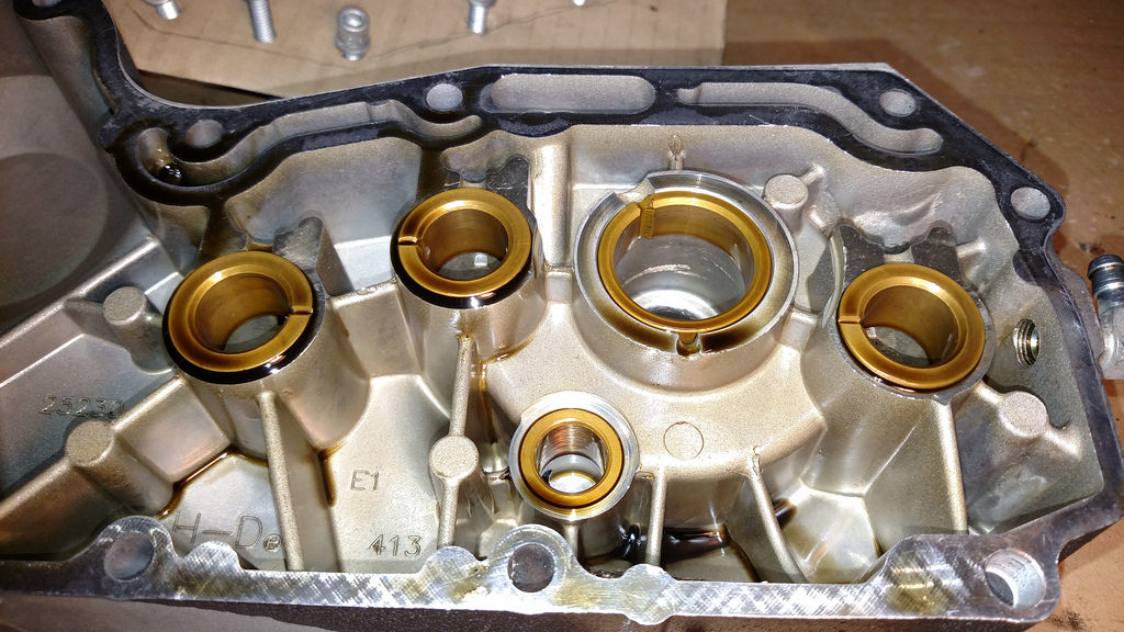
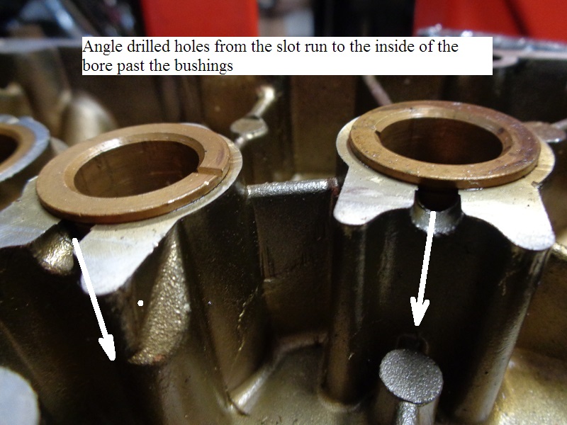
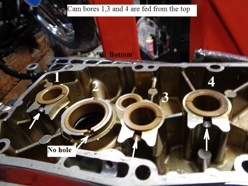
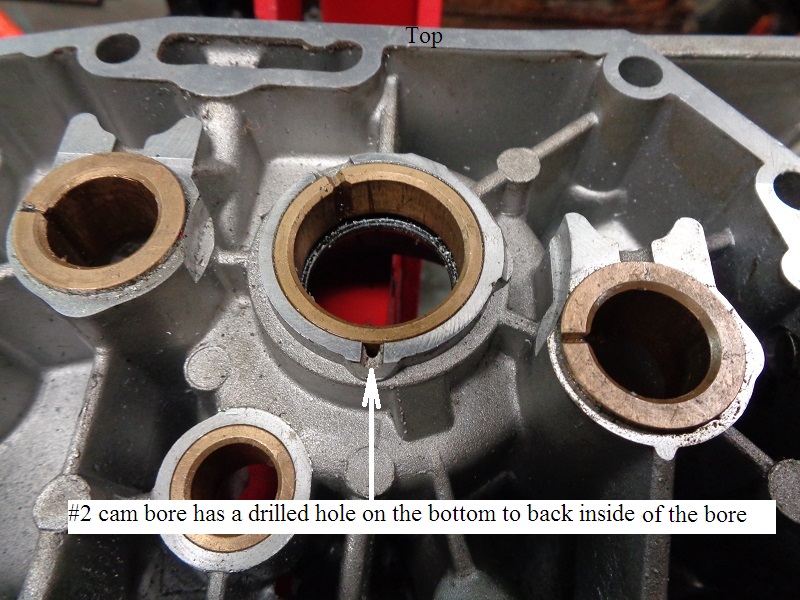
Outer Bushings
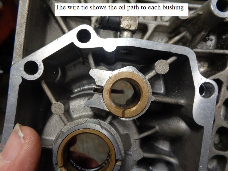
These bushings are fed from splash oil into channeled holes drilled behind the bushing faces.
#1, #3 and #4 cam bores have channels drilled from the top down into the back side of the bores.
The channel for #2 cam bore starts at the bottom and is drilled into the back side of the bore.
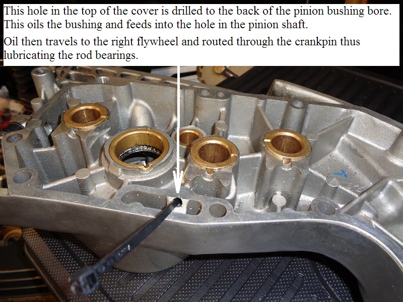
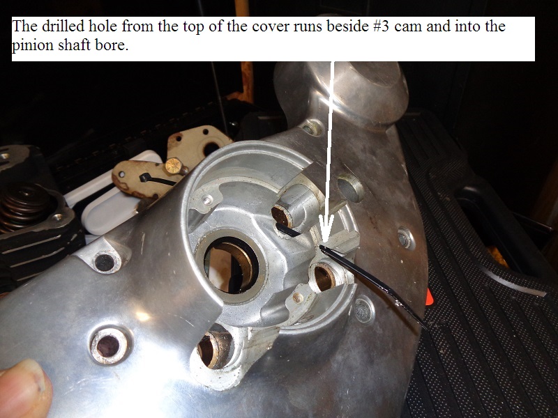
The pinion bushing (as well as the hole in the pinion shaft) is fed from a cross drilled hole in the top of the cover.
 |  |  |
 |  |  |
 |  |  |
Lifters (tappets)
Sub-Documents
See also in the Sportsterpedia;
………. Hydraulic Lifter - Disassembly / Inspection / Assembly
The stock Evo Sportster tappets (lifters) are hydraulic as opposed to being solid.
That is, they use oil to fill an internal cavity to create a stiff lifter to press upwards on the pushrod.
This oil-based operation allows the hydraulic lifters to self-adjust for minor changes in valve operation caused by heat expansion.
It eliminates the need for adjustable pushrods.
A hydraulic lifter self-adjusts within a certain range. 26)
In other words, if your pushrods are too long, the lifter automatically shortens, and if the pushrods are too short, it automatically lengthens.
The stock tappets are roller lifters as opposed to flat lifters.
There is a rolling wheel at the bottom of the lifter that rides on the cam lobe. \
There are opposing flat spots near the top of the lifter.
To keep the lifter's roller wheel aligned to the cam lobe, there are anti-rotation pins in place nearly up against those flat spots on the lifter.
Stock lifters can be inserted either way, so long as the roller wheel is aligned with the cam lobe and the flats are aligned with the anti-rotation pins afterwards.
1986-up Sportsters were fitted with hydraulic roller lifters (roller tappets) from the factory.
Parts below are for the updated versions from 1986-on.
- Each lifter has needle bearings inside a wheel that is held in place by a solid axle.
The wheels / bearings for 1991-up lifters cannot be replaced as the axle is not removeable. - Each lifter is compiled of 2 main bodies, an outer (lifter body) and an inner (cartridge body, AKA plunger).
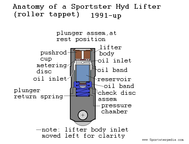
- Both the lifter body and plunger have a machined recessed area (oil band) around the outer circumference to circulate pressurized oil around it.
The lifter body also has an inner oil band to transfer oil to the internal body cartridge (plunger).
The oil bands insure oil is transferred to the inside of the plunger reservoir (no matter of it's inlet positioning). - There are two separate cavities; 1 in the bottom of the lifter body (pressure chamber) and 1 inside the plunger (oil reservoir).
The pressure chamber is what actually does the lifting on the engine valve.
The oil reservoir feeds both the pressure cavity and the rocker arms. - Sitting directly under the plunger is a check disc assembly.
There is a very thin solid disc smacked against the hole in the bottom of the plunger.
The disc is held against the plunger by a spring below it and both captured by a metal housing pressed onto the bottom of the plunger.
The disc opens allowing oil into the chamber and oil to leave the chamber at different times. - Sitting on top of the plunger reservoir a metering disc under the piston cup. Both the metering disc and pushrod cup sit on a shelf machined in the top of the plunger.
The assembly is held in place by a retainer clip fitted into the machined cup in the top of the lifter body.
The metering disc is another restriction in the oil path to regulate the amount of oil delivered into the pushrod.
More importantly, it retains a certain amount of pressure below it in the plunger reservoir to quickly fill the pressure chamber.
The pushrod cup is concaved to match the shape of the pushrod end that stacks on top of it.
Engine valve pressure creates a seal between these two parts.
The drawing below is of a 1991-1999 Sportster OEM lifter and shows the parts mentioned above. However, 2000-up Sportster lifters have the same parts.
Checking Lifter Pre-load
Hydraulic lifters self-adjust over about a .100” range, from .050“ preloaded to .150” preloaded. 28)
They'll actually work outside that range but they might make noise, so it's best to stay in that range.
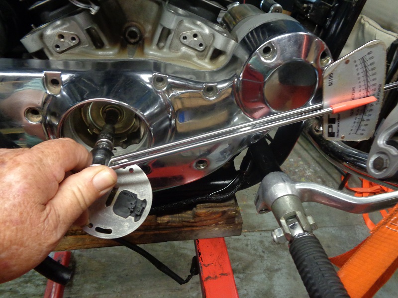
- Measure at the rocker box how much the lifter will get preloaded at the rocker box. 29)
- Put your pushrods in place (remember, the longer one goes on the exhaust).
- Set the gasket and rocker box on top, and start the four big screws only.
- Finger tighten the left (spark plug) side.
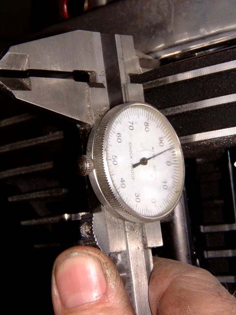
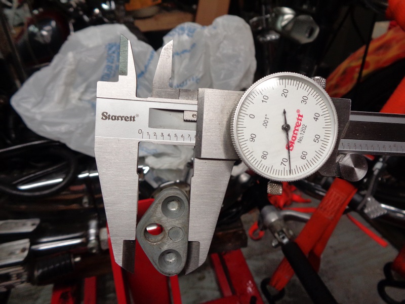
(while making sure the right side is resting with the upper pushrod ends sitting in the cups on the rocker arms) - Now take a simple caliper and measure how much gap you have between the rocker box and the rocker box gasket, as shown in the photo below.
- This won't be an exact answer, but it'll be pretty close.
Remember, you'd like to see the plunger preloaded about .100“, but anywhere between .050” and .150“ should work.
You can order pushrod lengths that are longer or shorter than your stock pushrods by the amount it takes to achieve .100” of lifter plunger preload.
If you don't have a caliper to measure your stock pushrod lengths, the information is available in most factory service manuals.
The lifter plunger should be preloaded between .050 and .150. Make the measurement if you're not sure.
 30)
30)
Oil feed to lifters
91 and up engines have a horizontal passage on the top of the cam box that is fed oil from the filter pad.
This horizontal passage feeds into the lifter bores.
Oil is fed internally to the lifter thru a small hole on the side.
The stock lifters can be inserted either way, so long as the roller wheel is aligned with the cam lobe and the flats are aligned with the anti-rotation pins.
| 91-99 engines have a single passage in that top area, the tappets are connected by internal passages from this small cavity. | On 2000 and up engines, oil travels to each lifter individually from this cavity. 31) |
 |  |
1986-1990 models
There was a running change in 1986 to new style hydraulic lifters as opposed to the original 1986 versions for Sportsters. 32)
They were the same as those used in 1340cc engines beginning in the 1986 model year. The change was to allow for one component to service the entire product line.
Per HD Service Bulletin M-930A;
Beginning with crankcase #1786 127 043 (883cc) and 1886 127 001 (1100cc), new style hydraulic lifters were installed at the factory.
New style lifters can be identified by the presence of notches in the pushrod socket.
Click here to go to the service bulletin page where you can download the service bulletin.
- A piece of wire can no longer be used to drain lifter during installation.
- After push rod lengths have been measured and the correct length push rods selected, remove lower rocker boxes.
- Rotate engine so both lifters from the cylinder being serviced are on the base circle (lowest position of the cam).
- Install push rods and push rod tubes. Install new gaskets under lower rocker box.
Place lower rocker box assembly (with rocker arms and shafts) in position.
Place push rods in rocker arm sockets. - Slowly snug all rocker box fasteners in small increments (one turn at a time).
Use a cross pattern on the four large bolts that fasten the lower rocker box to head.
This will bleed the lifters. Tighten fasteners to the correct torque. Refer to the 1986 XLH Service Manual for the proper tightening sequence.
CAUTION, Do not turn the engine over until both push rods can be turned with fingers to avoid damage to push rods or rocker arms. - Repeat Steps 2 through 5 for other cylinder
The oil feed to the lifters comes from the oil pump, through a passage in the cam cover to the feed galley in the top of the right case.
The intake lifters are fed oil from the feed galley hole. Each exhaust lifter is fed from it's corresponding intake lifter bore.
| 1986-1990 lifter oiling path 33) |
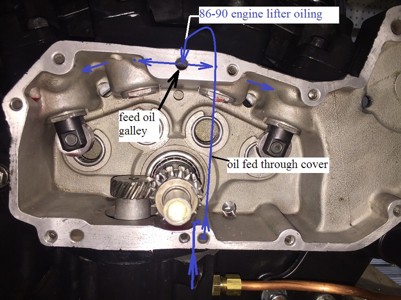 |
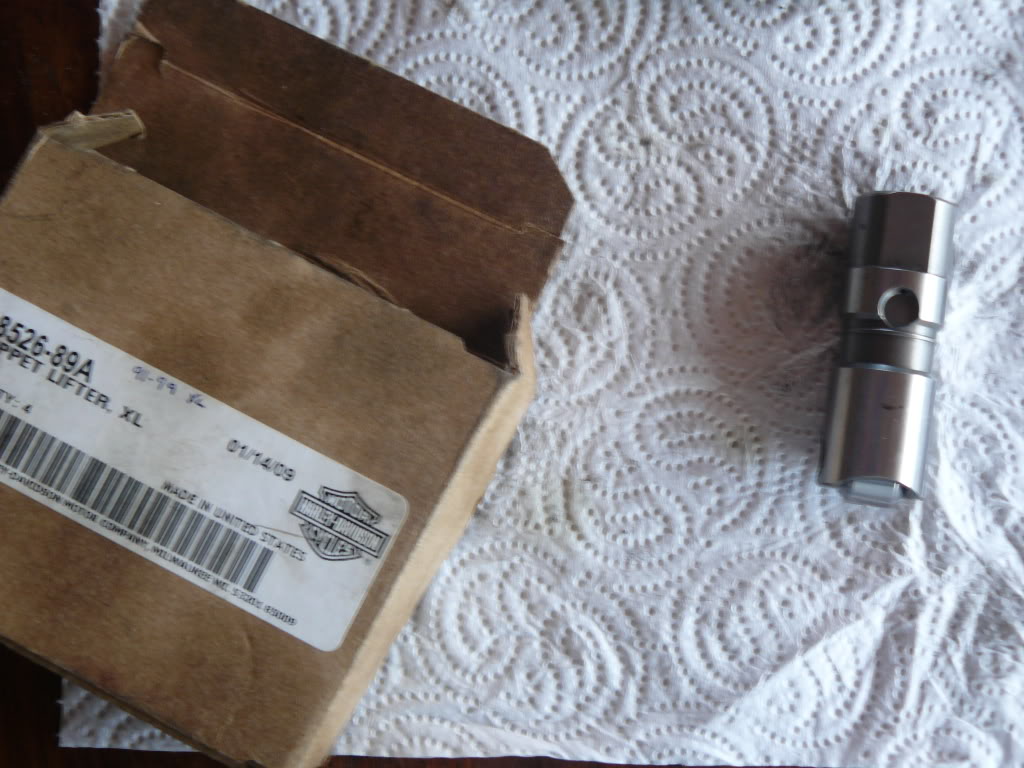
91-99 Lifters
1991-1999 engines have AMC-Mopar style lifters (.903“ diameter). 36)
| 1991-1999 lifters (18526-89A) 37) | ||
 |  |  |
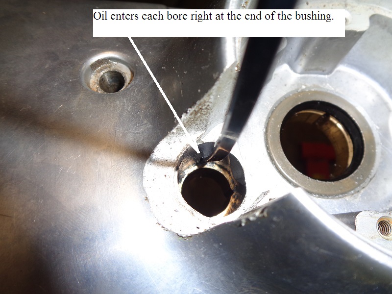
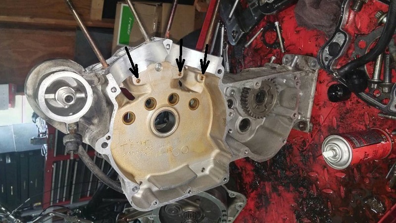
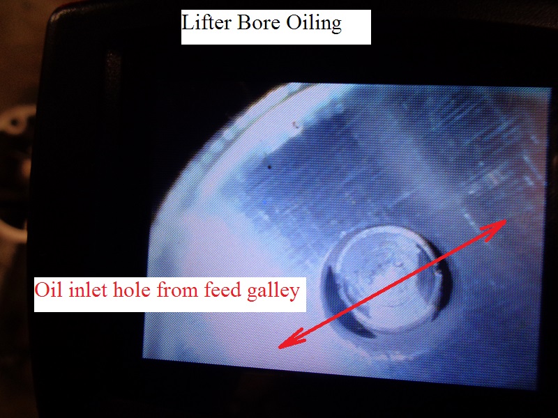
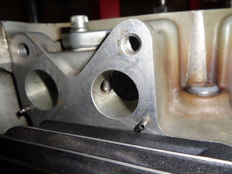
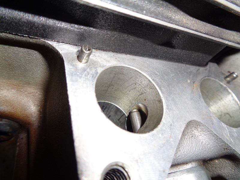
The oiling hole for the lifters in 1991-1999 engines is drilled from the inside of the right case out through the lifter bore and into the case oil galley.
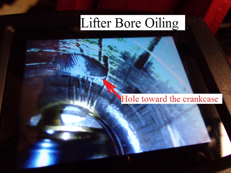
All four lifter bores are capped on the inside of the right case. This left a blind hole between each lifter toward the inside of the case.
| 91-99 lifter bore 40) | |
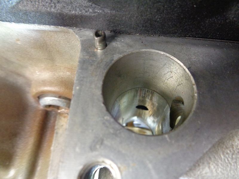 | 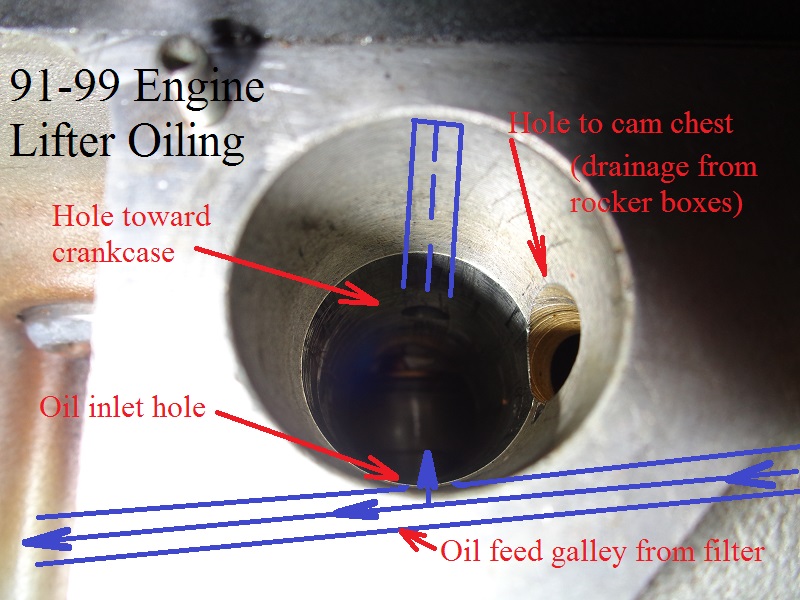 |
| A look inside the oiling holes in the lifter bore on a 91-99 case. Notice the capped hole toward the case in the third pic. 41) | ||
 |  |  |
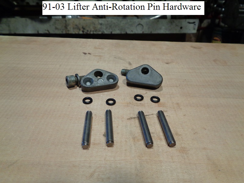
91-99 Anti-Rotation Pins
Parts:
4 - screws (884)
4 - washers (6099)
2 - pin plates (36804-89)
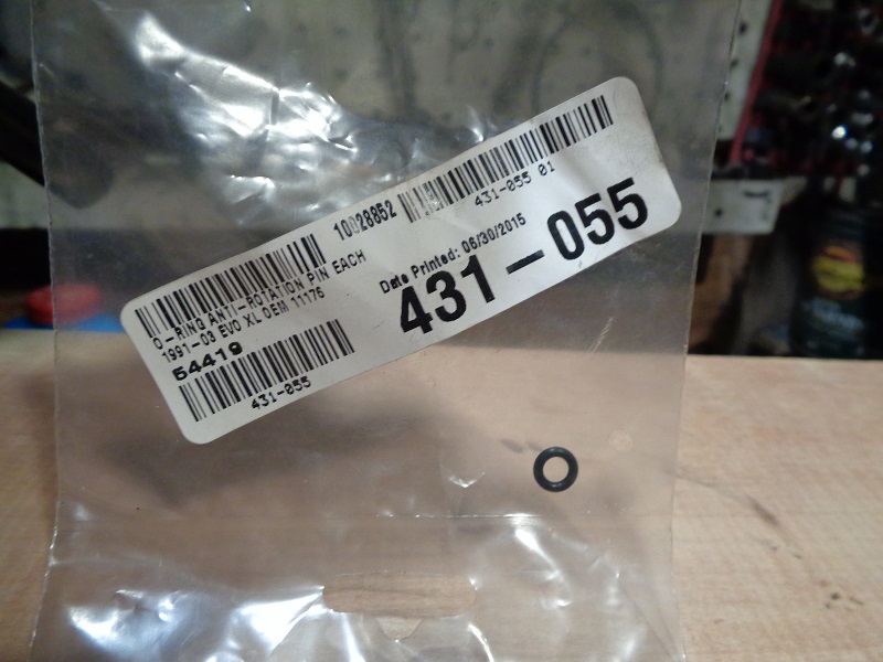
4 - O-rings (11176)
4 - anti-rotation pins (18532-89)
Torque: 80-110 in. lbs. (9.0-12.4 Nm) 42)
| 91-99 anti-rotation pin hardware 43) | ||
 |  |  |
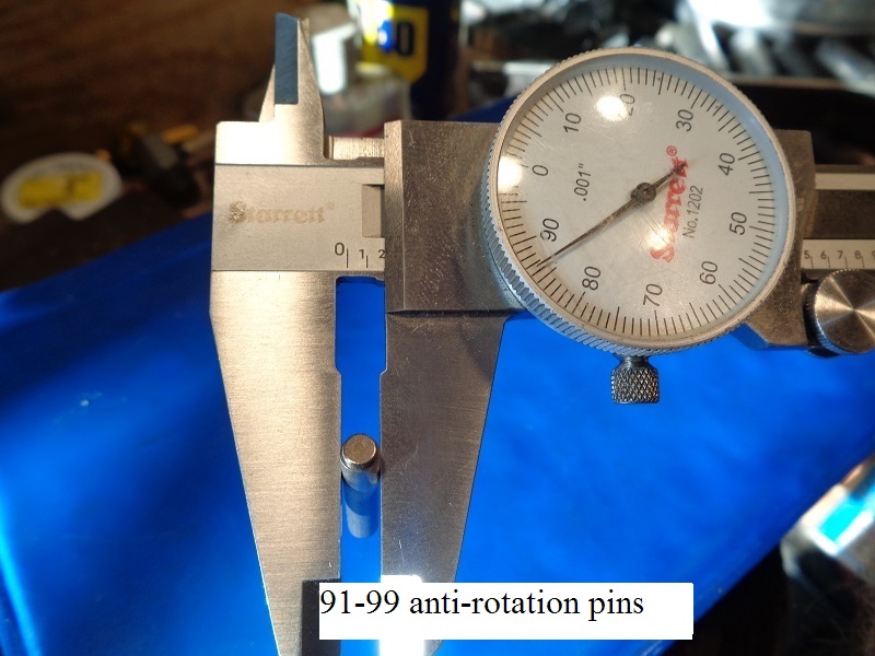
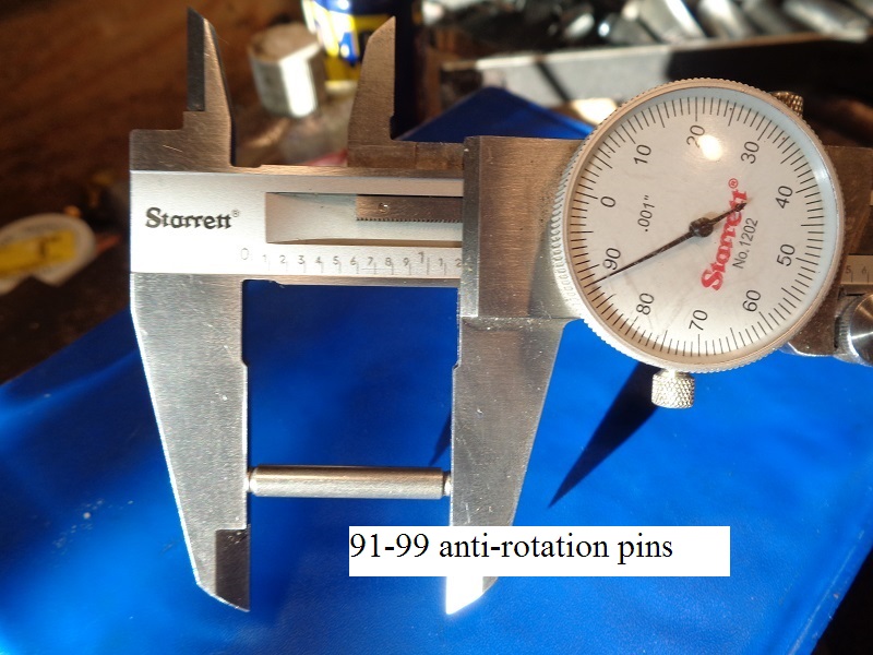
| App. pin dims 44) | |
 |  |
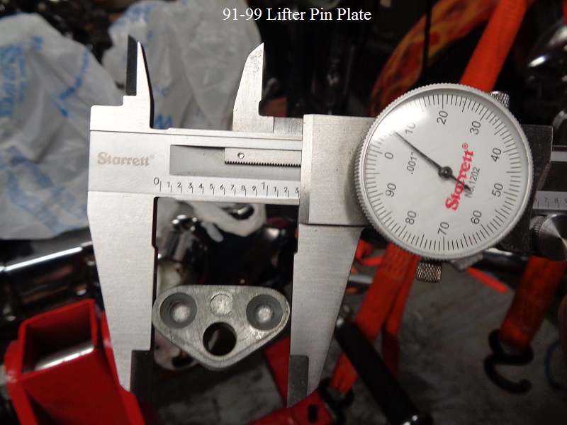
| App. pin plate dims 45) | ||
 |  |  |
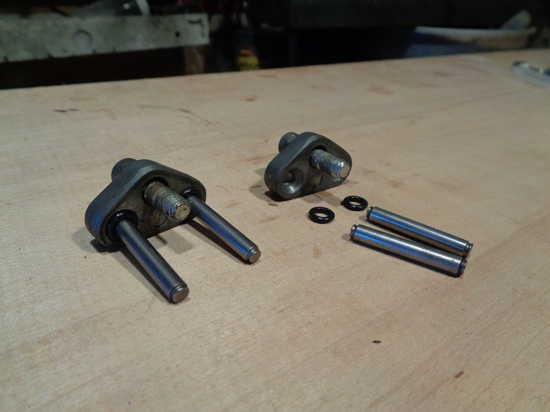
| Slide the pins in the holes, install the O-rings over the pins. 46) | ||
 |  |  |
| Then install the plate and torque to 80-110 in lbs. 47) | ||
 |  |  |
2000 and Up Lifters
2000 and up have GM/twin cam style lifters (.842” diameter). 48)
| Lifter from an 02 XL883 49) |
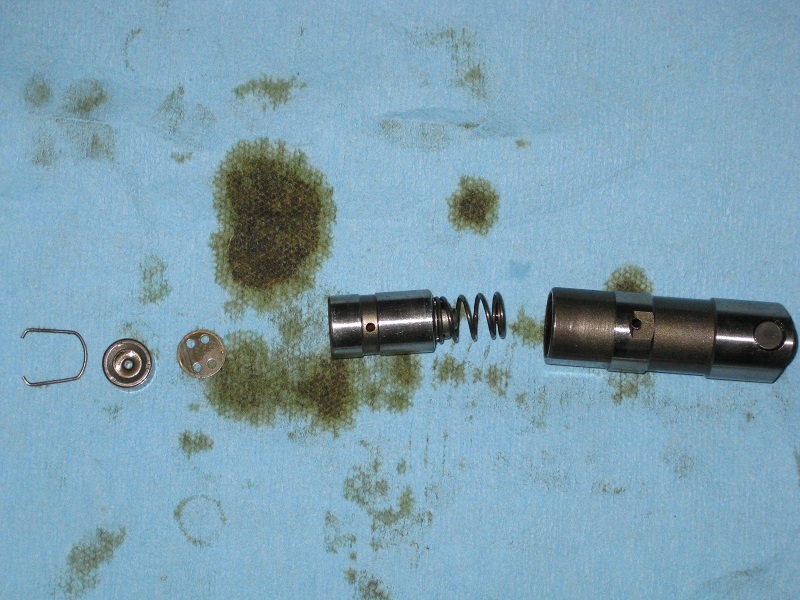 |
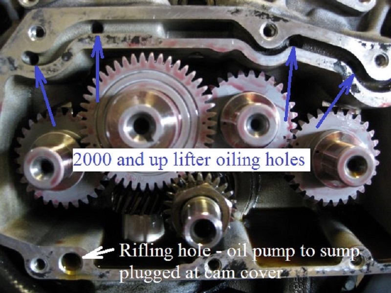
2000 and Up engines:
However, the oil galley was now cut into the right case instead of a rifle drilled hole.
This made it easy to drill oiling holes to the lifters from the outside of the case into the lifter bore.
So there were no lifter oiling holes to cap on the inside of 2000 and up cases.
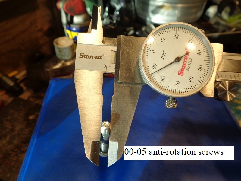
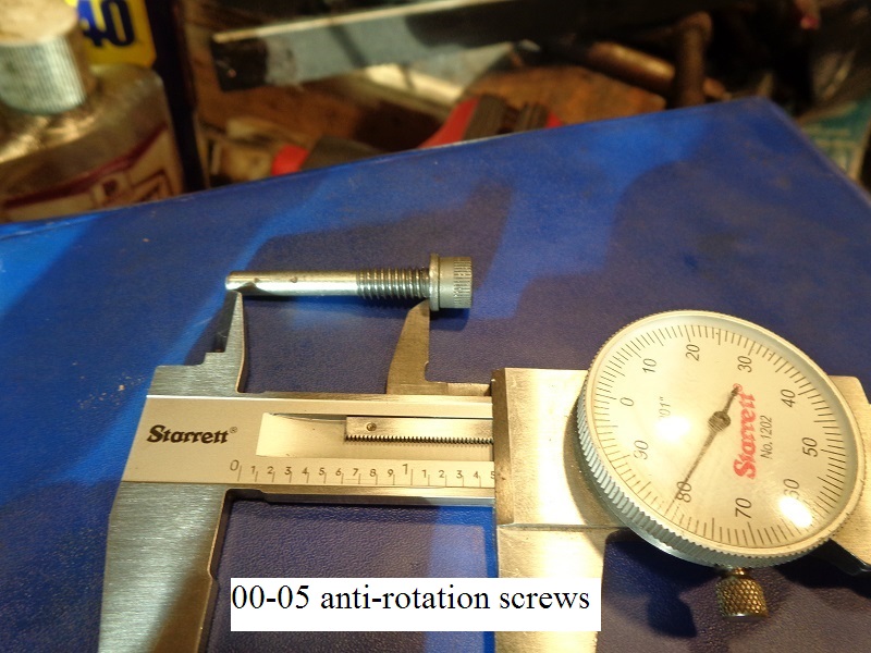
00-05 Lifter Ant-Rotation Screws
Parts:
4 - anti-rotation screws (18532)
This is the redesigned version of the anti-roll pins.
Comprised of a single pin for each lifter as before (4 in all).
However, this is a one piece design that is threaded into the case with no holding plate.
Torque: 55-65 in. lbs. (6.2-7.3 Nm) 52)
| 00-05 anti-rotation screws 53) | App dims (photos by Hippysmack)) | |
 |  |  |
| End of screws run up into the case. 54) | |
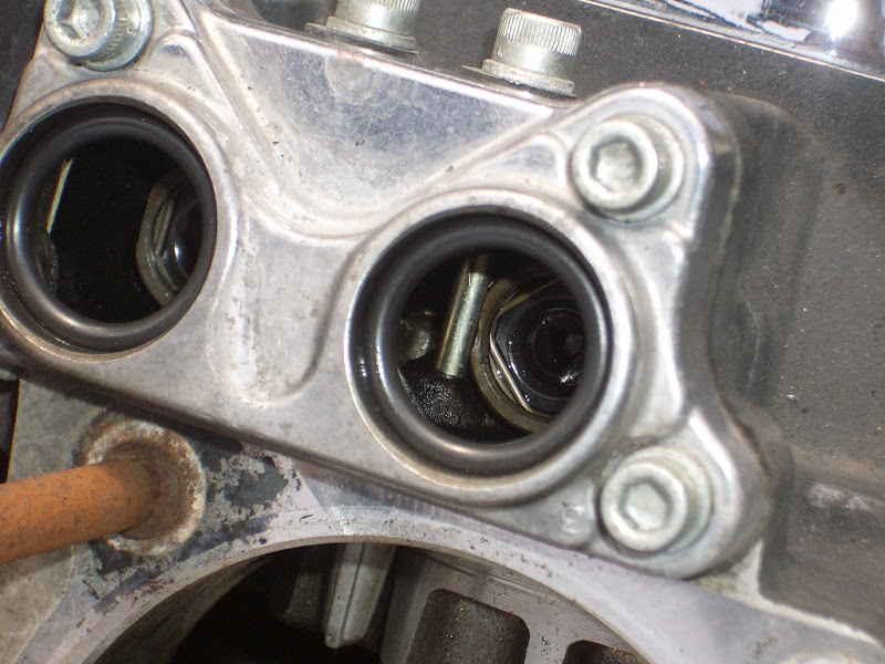 |  |
06-Up Anti-Rotation Device
Parts:
2 - Anti Rotation Device blocks (18505-06)
The ARD is a flexible piece of plastic that is designed to flex in operation to allow for an imperfect lifter bore location. 55)
It is designed for lifters that have a flat cut on each side.
These work OK for stock cams.
But if you're upgrading to bigger cams, anything more than .600 lift has too small a base circle. 56)
(and they will nearly drop out of the ARDs and they can also spin away from them)
The big issue is that they turn sideways with the roller not turning on the cam lobe.
(which can heat up and destroy the roller and the cam lobe)

Pinion Gear
- Removal / Installation of the Pinion Gear:
- Lock the pinion shaft itself, not from the brake pedal, primary side, pistons or anywhere else:
It's very important to hold the crank still from the gearcase side to torque the pinion nut on or off (usually done by holding the pinion gear still).
If you, for example, put the bike in gear and hold the rear brake and torque on the nut, you run the very real risk of knocking the crank out of true.
(which requires a full tear-down to fix).
It's not designed to transmit torque from one side to the other and it tries to twist the crankpin connection.
You'll need a tool to lock the pinion gear for removal or installation. See tool options in the REF section of the Sportsterpedia.
Again, holding the flywheel still by any method on the other side of the flywheel assembly or top side runs the risk of knocking the wheels out of true. - Pinion Nut:
Torque Specs:
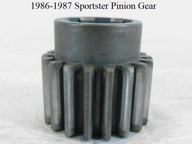
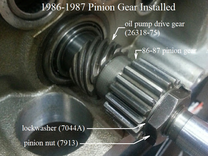
The 86-87 pinion gear is located by 6 internal splines mating between 6 external splines on the pinion shaft.
There is a lockwasher (7044A) between the nut and the pinion gear.
Pry the tabs on it up to remove the pinion nut, bend them down against the flats on the nut to install.
Factory torque is (35-45 ft/lbs.)
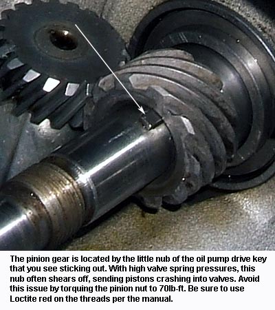
The 1988-up pinion gear is located by a little nub of the key that sits under the oil pump drive gear.
That little nub is not nearly strong enough by itself to keep the gear from shearing on the pinion shaft.
And instead, it's the clamp load from the nut that keeps the pinion gear where we want it.
The factory torque spec on the pinion nut (35-45 ft/lbs).
Per Hammer Performance, that has proven woefully inadequate to hold the pinion gear in place (esp. with high pressure valve springs).
They highly recommend using 70 ft/lbs of torque instead 59) (as do other performance shops, Zippers cam instructions etc,).
Loctite:
Use red Loctite on the shaft threads per the manual but don't just slather it all over the threads.
All it takes is a light bead around 2 or three threads (in the middle of where the nut will end up when tightened.
There is no reason to use Loctite on the nut.
Compatibility 60)
1986-2003 parts books do not list a part number for the pinion gear and it appears the pinion gear is part of the cam gear set (not sold separately).
However, a gear could be ordered from the MoCo. The part# coincides with the color scheme coding on the respective cam sets.
2000-up pinion gear part number is (24047-00) as appearing in the 2004-up parts catalogs.
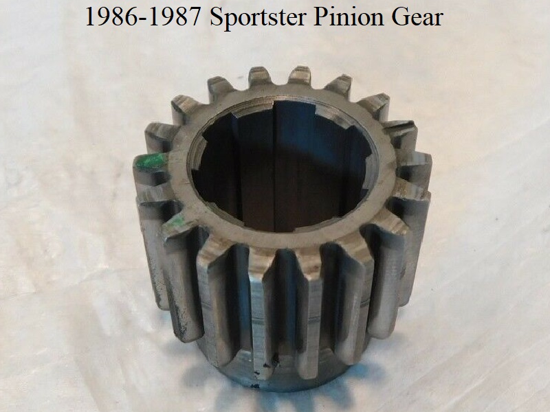
1986–1987 pinion gears have a (6-spline) pinion shaft.
1988-up pinion gears have no splines and have a notch out the back side (not under) to slide around a woodruff key on the non-splined pinion shaft.
1986-1999 pinion gears have the same coarse (13) tooth pitch.
2000-up pinion gears have a fine (23) tooth pitch.
XL Pinion Gear Color/Size Info here:
http://xlforum.net/forums/showthread.php?t=1963918
Part numbers and color coding:
1986-1999 cams continued the color coding as in previous years for optimum noise reduction in the gear mesh.
However, from 1986-1990, there were even more color combinations including cam drive gear sizes.
Each factory pinion gear was colored coded with a dot (even though it was more like a splotch at times) that matched the same colors on the matching cam drive gear.
1986-1990 cam drive gears came with either one dot or two dots. Their corresponding pinion gear also came with one or two dots respectively to that gear set.
1991-1999 cam drive gears were only colored with one dot and likewise, there will only be one dot on their respective pinion gear.
2000-Up factory pinion gears have no color codes.
 | |
||||||||||||||
|---|---|---|---|---|---|---|---|---|---|---|---|---|---|---|---|
| Factory Pinion Gears by Part Number and Color of Dots (★ = 1 Dot, ★★ = 2 Dots) | |||||||||||||||
| 1986-1987 Sportster | 1988-1990 Sportster | ||||||||||||||
| Part# | Brown | Blue | Red | White | Green | Yellow | Black | Part# | Brown | Blue | Red | White | Green | Yellow | Black |
| 24055-86 | ★ | 24055-88 | ★ | ||||||||||||
| 24056-86 | ★ | 24056-88 | ★ | ||||||||||||
| 24057-86 | ★ | 24057-88 | ★ | ||||||||||||
| 24058-86 | ★ | 24058-88 | ★ | ||||||||||||
| 24059-86 | ★ | 24059-88 | ★ | ||||||||||||
| 24060-86 | ★ | 24060-88 | ★ | ||||||||||||
| 24061-86 | ★ | 24061-88 | ★ | ||||||||||||
| 25737-86 | ★★ | 25737-88 | ★★ | ||||||||||||
| 25738-86 | ★★ | 25738-88 | ★★ | ||||||||||||
| 25739-86 | ★★ | 25739-88 | ★★ | ||||||||||||
| 25740-86 | ★★ | 25740-88 | ★★ | ||||||||||||
| 25741-86 | ★★ | 25741-88 | ★★ | ||||||||||||
| 25742-86 | ★★ | 25742-88 | ★★ | ||||||||||||
| 25743-86 | ★★ | 25741-88 | ★★ | ||||||||||||
| |
||||||||||||||
| Factory Pinion Gears by Part Number and Color of Dots | |||||||||||||||
| 1991-1999 Sportster | 2000-Up Sportsters | ||||||||||||||
| Part# | Brown | Blue | Red | White | Green | Yellow | Black | Part# | 24047-00 | No Color Coding | |||||
| 24055-91 | ★ | ||||||||||||||
| 24056-91 | ★ | ||||||||||||||
| 24057-91 | ★ | ||||||||||||||
| 24058-91 | ★ | ||||||||||||||
| 24059-91 | ★ | ||||||||||||||
| 24060-91 | ★ | ||||||||||||||
| 24061-91 | ★ | ||||||||||||||
1986-1987 Sportster (18T) Pinion Gear:
Has internal splines.
 61)
61)  62)
62)  63)
63)
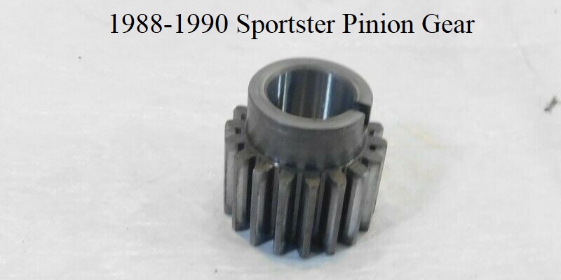
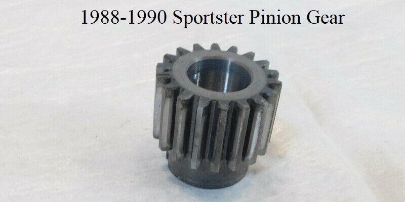
1988-1990 Sportster (18T) Pinion Gear:
Has a notch cut out of the rear for the woodruff key (T-key) on the pinion shaft and no splines.
 64)
64)  65)
65)
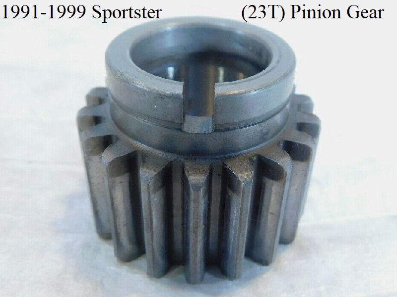
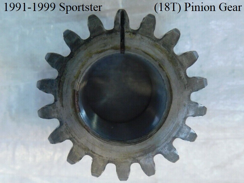
1991-1999 Sportster (18T) Pinion Gear:
Has a ring cut around the circumference of it's rear sleeve, a notch cut out of the rear for the woodruff key (T-key) on the pinion shaft and no splines.
The ring around the sleeve may just be to distinguish the 91-99 gear from the 88-90 gear.
 66)
66)  67)
67)
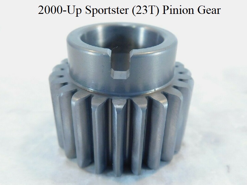
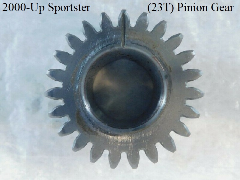
2000-Up Sportster (23T) Pinion Gear:
The ring around the rear sleeve was deleted, has a notch cut out of the rear for the woodruff key (T-key) on the pinion shaft, finer gear mesh and no splines.
 68)
68)  69)
69)
Possible 91-up Woodruff Key Failure Notice
There is a bronze oil pump gear available which is considered an upgrade but that won't stop the key from shearing.
Read more about the oil pump drive gear failure and upgrade here in the Sportsterpedia.
The woodruff key on the pinion shaft has been subject to shearing.
Click Here for more information in the Sportsterpedia.
Timing Cup (Rotor)
| Timing cup bolt thread size: #10×32 Wrench size: 5/16“ Torque: 43-53 in/lbs 71) Use Loctite 242 (blue) on the bolt threads 72) |
 |
| Installing timing cup bolt on a 98 1200S 73) |