Table of Contents

EVO: Engine Mechanicals - Sub-02C
Hydraulic Lifter - Mechanical and Hydraulic Operation
The hydraulic lifters used in HD motors have about .200 of (useable) plunger travel 1) (about .230“ if they bottom out, which is not good).
As long as it's preloaded between about .050 and .150, it adjusts itself properly. So in other words, there's about a .100” range of pushrod length.
The lifter will automatically adjust it's length to make it all work properly.
System oil pressure goes all the way thru the lifters to the rocker boxes.
However, system pressure at the lifter bore is restricted several times before it gets delivered into the pushrod tubes to the rocker arms.
Pressure and flow is lowered entering the path to the plunger, further lowered to the reservoir, further lowered entering the pushrod.
System pressure also builds (from a lowered state) during the process by wide oil bands, the plunger reservoir and of course engine valve pressure.
Examining internal lifter oil paths from the lifter bore to the rocker arms will show some of these dynamics.
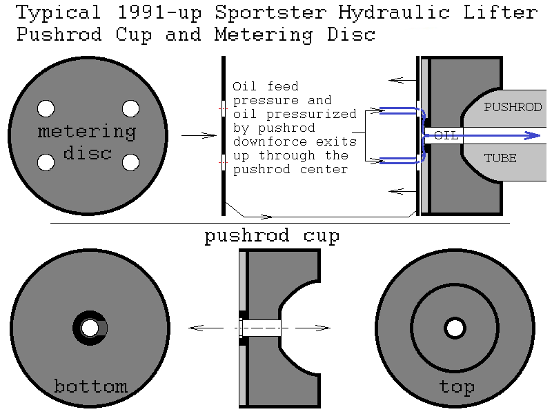
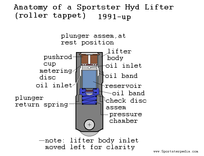
Below is an animated drawing (.gif) of 1991-1999 Sportster lifter operation and oil feed. However, 1991-up lifter action are the same.
It examples the text below in operation.
Disclaimer:
The main oil inlet in the lifter body has been moved to the left side for clarity of the feed path.
Also, the oil inlet is slightly lower than the actual part but operation and paths are the same.
Oil to the lifter body
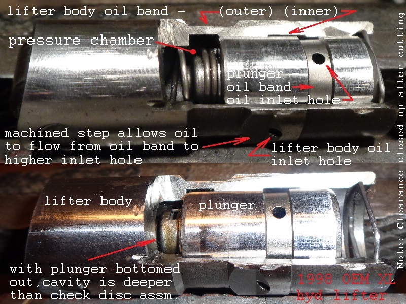
System oil pressure is fed through the lifter bores into the outer oil band that circles the lifter body.
Oil circles around the lifter body's outer oil band and finds it's way into the oil inlet hole above the oil band.
There is a machined taper above the outer oil band up to the inlet hole that allows oil to rise to the inlet.
The hole is angle drilled in the lifter body so that it opens into the oil band of the plunger body.
The inlet hole is much smaller than the feed path. So system pressure is reduced past the hole.
A smaller amount of flow runs (faster) through that drilled passage through the lifter body wall.
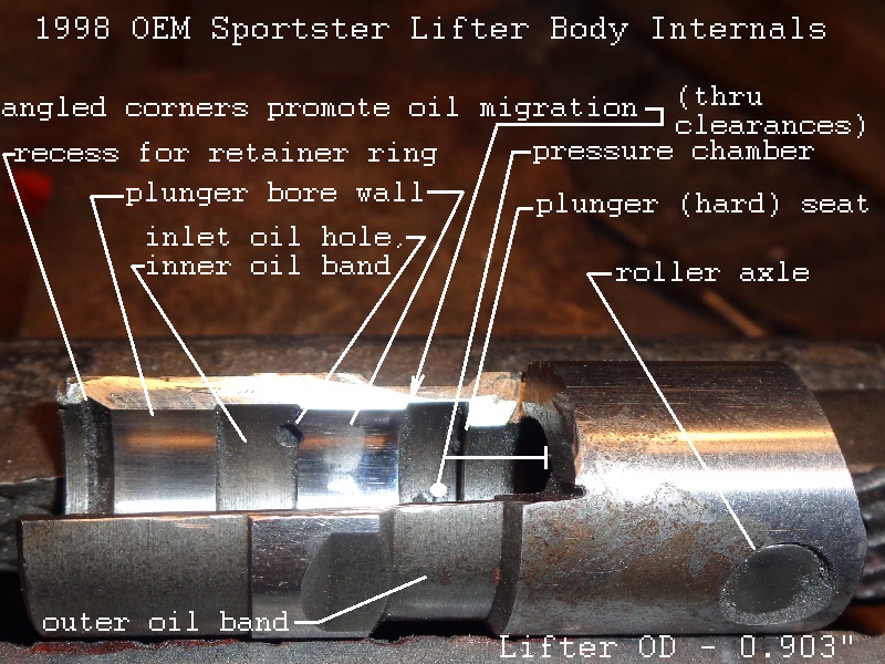
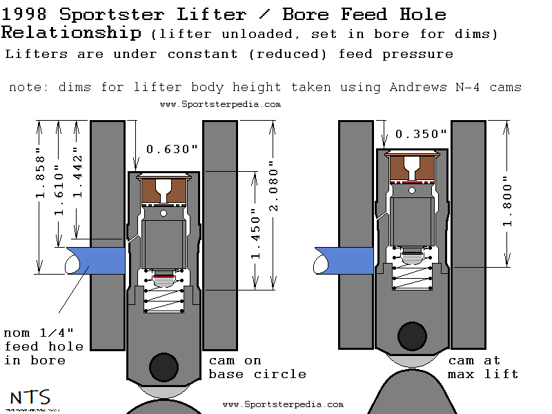
In the drawing below, dims were taken from a 1998 1200S lifter and bore showing that oil feed is never blocked to the lifter.
The cams are Andrews N-4s so actual lift may vary. However, the feed hole in the bore should be the same for at least 1991-1999 Sportsters.
 5)
5)
Oil to the plunger reservoir
Oil from the lifter body inlet enters a small area between the inner body and outer plunger body.
The clearance between body and plunger is tiny.
This tight clearance allows the plunger to move up and down without metal to metal contact to the lifter body.
The clearance creates a sliding oil seal between them in operation, allowing back pressure to build.
Increased wear, opening up this clearance between these walls, can reduce pressure to the rocker arms.
Side note: The restricted orifice in the pinion shaft allows pressure to build at the lifter bores as well.
Without the pinion shaft restriction, there wouldn't be as much pressure to push oil through the restricted lifter holes.
The internal clearance between body and plunger is also where the lifter bleeds off (very slowly) when the cam is off the base circle (as the lobe rises and falls).
Due to the tight oil seal between the lifter body and plunger, oil pressure can be transferred through the path to the rocker arm.
There is an inner oil band in the body that mates around an outer oil band of the plunger between the clearance zones between them.
The oil here is subject to variable pressure changes as the plunger rises and falls due to oil band construction and position.
The oil bands pocket depths are different and the combined dimension when they meet up changes depending on plunger positioning.
Oil is transferred to the plunger inlet by way of these two oil bands meeting together forming a single (circular) path.
With the cam on it's base circle, the combined dim is the widest and most the highest amount of oil flow gets to the plunger reservoir, thus rocker arms.
As the cam lobe rises, the combined dim decreases and the least amount of oil is sent to the reservoir.
This lowers oil flow to the reservoir and rocker arms until the cam returns to it's base circle once again.
The plunger has an oil inlet in the middle of the surrounding oil band that allows oil to enter the reservoir inside.
The oil bands insure oil transfers to the plunger reservoir inlet hole (no matter of it's positioning).
The plunger is free to rotate invariably both during assembly and when not under load.
Role of the check disc
Sitting under the plunger is a thin metal disc with no holes in it that blocks oil from entering / leaving the pressure chamber below.
The disc has a spring below it and the spring tension comes from a metal cage that presses the assembly together.
The metal cage presses onto a boss under the plunger.
The check disc allows oil to leave the pressure chamber when the cam lobe ramp initially rises off the base circle.
It opens due to momentary vacuum (or differential pressure) created in the pressure chamber a minimum of twice per cycle.
Immediately afterwards, positive pressure (whether spring loaded or hydraulic force) closes the check disc against the bottom of the plunger.
Oil to / from the pressure chamber
Oil is forced out of the pressure chamber into the reservoir when the cam lobe initially rises.
As the camshaft rotates and opens the engine valve, the pushrod (thus the lifter's plunger) is forced down toward the bottom chamber. 7)
The downward force of oil in the plunger reservoir opens the check disc toward the lower chamber.
The (now open bottom) plunger is moving down into the lower chamber filled with oil.
Some of the oil in the lower chamber is squeezed up past the open check disc into the plunger reservoir.
With the check disc open, the lower chamber volume decreases as the plunger is continuously forced toward it by increasing engine valve spring pressure.
This increases oil pressure in the lower chamber forcing the check disc to close toward the plunger.
As oil is considered incompressible, the plunger can no longer move since oil is trapped under it in the lower chamber (except thru the very tight clearance).
The lifter now operates as a solid lifter and transfers the motion from the camshaft lobe to the pushrod / rocker arm.
Oil is allowed into the pressure chamber from the reservoir when the cam is on it's base circle.
During the lift of the camshaft and due to valve spring pressure, some of the oil in the pressure chamber is forced from the lifter cavity by the time of max lift.
Once the cam rotates back to it's base circle, the pressure from the pushrod is decreased on the plunger and it enters its at-rest position. 8)
Then the big spring under the plunger pushes the plunger up creating a negative pressure in the chamber thus opening the check once again.
Plunger reservoir oil pressure quickly slips thru the check disc opening into the pressure chamber and the check closes under it's own spring pressure.
The pressure chamber is now replenished with oil and ready for the next cycle.
This also re-sets the plunger height taking up the clearance between the pushrod and rocker arm creating zero lash.
Oil to the pushrods
Oil is not allowed to simply flow straight through from the plunger reservoir up into the pushrod.
Sitting atop the plunger reservoir is a thin metal disc with 4 small holes (metering disc) drilled through it.
Oil has to run through these holes to further the path up top.
The holes are in the neighborhood of .090“ each. This might not sound like a lot metering.
But oil through these holes gets restricted once again by the pushrod cup directly on top of the metering disc.
The pushrod cup mates to the metering disc by way of pressure just like the pushrod seals to the cup by way of pressure.
However, there is a machined inner cavity on the bottom of the cup where oil through the metering disc lands.
Oil circulates around the bottom of the cup until it reaches the center where there is another restriction in the path.
The cup machining basically creates a dish on the inside bottom where the sides and the center mate to the metering disc.
The center has a small slot milled out for oil to enter it, turning North up through the center into the pushrod.
The dish on the bottom is app 0.015” deep, the center slot is app .008“ deep and app 0.77” wide.
So there is a lot more oil that can pass through the metering disc than what can get through the cup's center all at once.
The restrictions in the pushrod cup also ensure that there will be back pressure in the reservoir to quickly fill the pressure chamber when needed.
And the pressure chamber is what actually raises the engine valves.