Table of Contents

REF: Oiling & Lubrication
Measuring Feed Oil Volume (flow rate) of the -72 Gear Type Oil Pump
Article by Kurt C. Melancon
See also Measuring Output Volume (flow rate) of a Gerotor Oil Pump in the Sportsterpedia.
Click on any pic below to enlarge.
Objective
- Quantify output of 1972 style Harley XL gear type oil pump (-72).
- Install a bypass circuit in the pump and quantify feed stream and by-pass stream volumes at various bypass pressures.
Oil Pump
The pump tested here consisted of a new -72 pump body, gears, and breather rotor, and was further modified to incorporate a bypass circuit that fractionated the pump output into a feed stream and a bypass stream. The ratio of feed stream to bypass stream volume could be altered by changing the spring force on the bypass valve. The pump was ultimately intended for use on a ‘56 KHK engine, where oil scavenging ability was a concern.
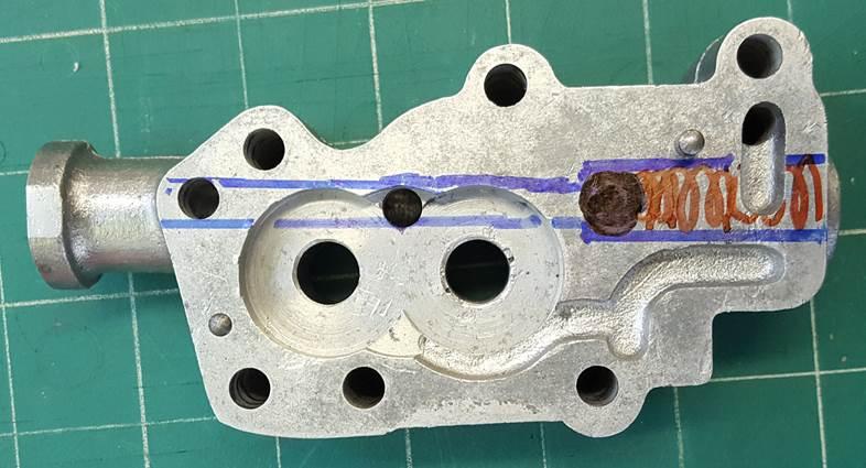
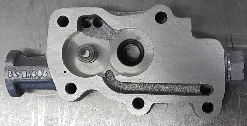
The image below illustrates the bypass modification made to the pump. A drill-way was installed from the front of the pump to the rear of the pump as shown by the blue lines. At the rear of the pump, the drill-way was enlarged to receive a check ball (shown in black) and a spring (shown in red) to seat the check ball. The combination of spring and check ball constitutes the valving system of the bypass circuit. The rear end of this check ball/spring hole was threaded so that spring pressure on the check ball could be adjusted, via different length slugs that altered spring force, and in turn alter the feed-to-bypass ratio. A hole was drilled down into the pump body to connect the bypass channel to the return oil channel (under the red spring).
Note, this is a 1956 pump body used here for (illustrative purposes only) of the bypass mod made to the -72 pump.
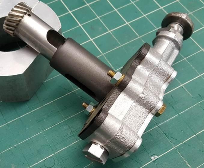
The completed modified -72 pump body is shown below.
The bypass circuit is installed as well as an alteration to feed inlet oil to the pump via the 1956 KHK inlet location on the case.
Testing Apparatus
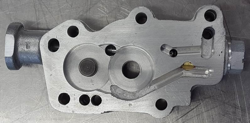
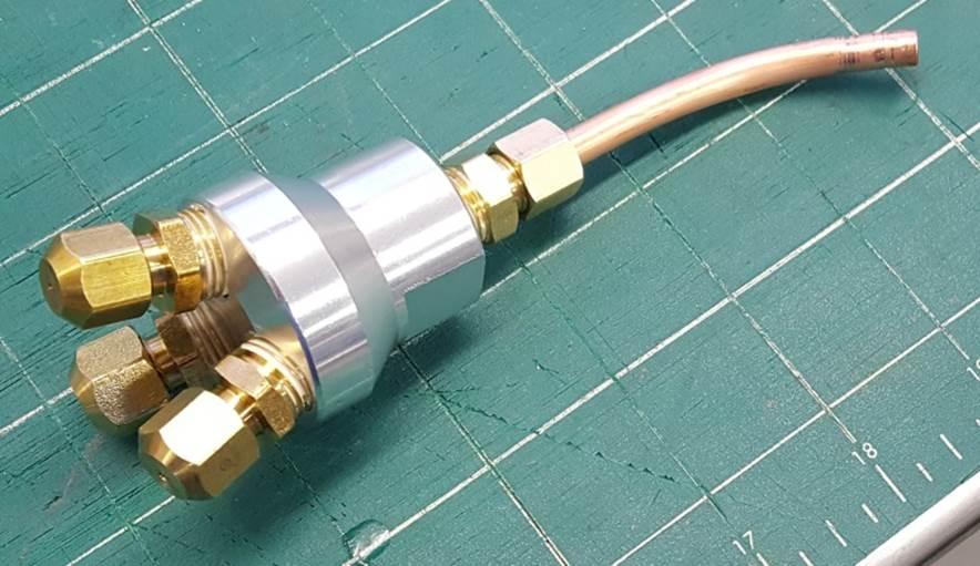
A mounting/distribution block with appropriate inlet and outlet orifices was made to mount the pump and support it during testing.
The images below show the mounting/distribution block.
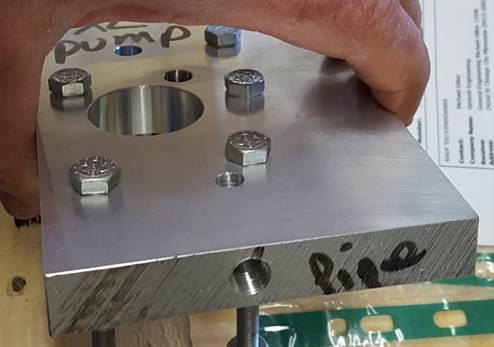
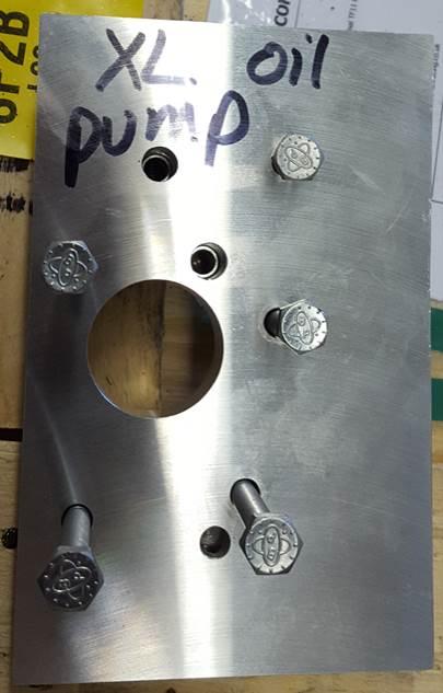
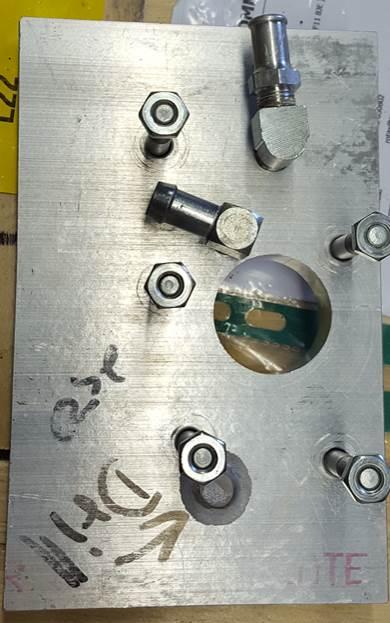
Pump connections consisted of a supply line and 2 return lines – one from the bypass circuit and one from the feed circuit, with the output of each return line collected in separate vessels during testing. The pressurized output feed line was fit with the following components, listed in the order they occur (1st listed is closest to the pump body).
- Pressure gauge
- Needle valve (controls the ratio of feed oil to bypass oil by changing the pressure head against which pump operates)
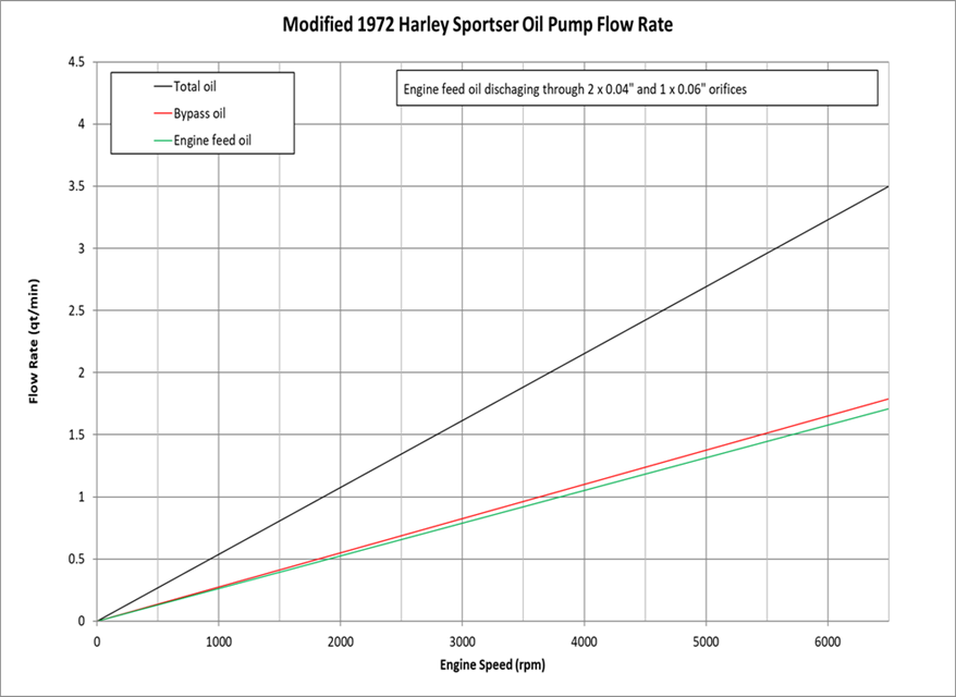
- Discharge orifice – aka “Cow Udder” as shown in the images below, had 2 x 0.040” dia orifices and 1 x 0.060” orifice.
“Cow Udder” manifold
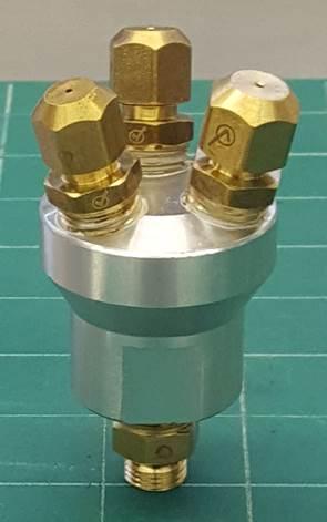
The “cow udder” restrictions described above represent a pressure head similar to that found in the KHK engine configuration, against which the pump operates. In this specific case a 0.060“ dia pill was installed in the end of the pinion shaft and a 0.040” dia factory piston squirter is found in the bottom edge of the bore in each KHK cylinder. During pump testing, throttling down the needle valve further increases the pressure head the pump operates against. As the needle valve is gradually closed, the pressure on the output line increases and the output flow decreases, as oil flow favors the circuit of least resistance, which in this case is the bypass circuit. In general, when the valve was throttling back the output flow, the bypass flow volume increased by approximately the same volume that was lost from the output flow.
The pump was driven using a lathe, with a rubber coupling connecting the pump to a stub in the lathe chuck. The pump was fed oil from a 1/2 gallon open vessel positioned on the head of the lathe. The feed oil and bypass oil were collected in 1 liter graduated disposable beakers positioned below the lathe ways. A stopwatch was used to measure pump operation time for determining flow rates (volume/time). The majority of runs were conducted at 500 lathe rpm (1000 engine rpm) with only select runs occurring at 1250 lathe rpm (2500 engine rpm).
Testing Materials
All testing was performed at room temperature. However, at room temperature oil has relatively high viscosity so may not necessarily represent hot oil being pumped in an actual engine. To address this concern and simulate actual pumping of motor oil at operating temperature, a blend of WD-40 and 5W-20 motor was made. More specifically, Fleet Farm 5W-20 semi-synthetic oil containing ~ 30 wt% WD-40 was employed to provide a fluid having a room temperature viscosity of ~ 20 cP, which is the same viscosity as straight 50 weight motor oil at 100°C. The plot below shows a dilution curve of the subject fluids mixed in various proportions.
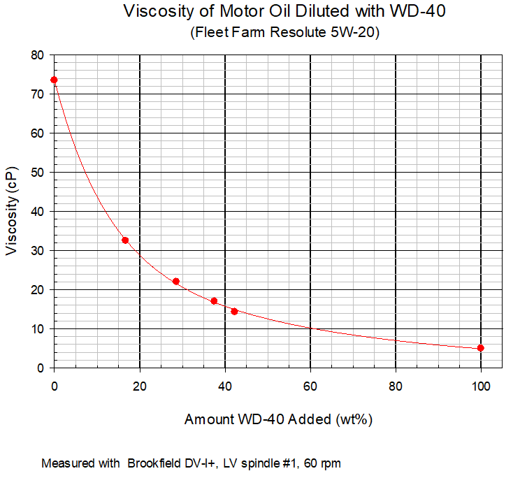
The subject test fluid was used almost exclusively, but a few runs were conducted with conventional oil - straight Mystik JT8 15W-50 motor oil at room temperature - to compare results with those from the low viscosity 20 cP blend.
Results and Discussion
It is well known that gear pump output, under controlled conditions, correlates linearly with pump speed, so pump output can be extrapolated to higher operation speeds with good confidence.
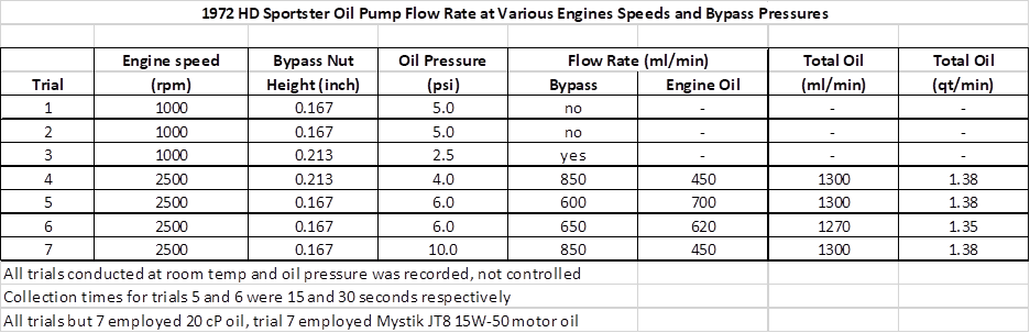
The data table and plot below show select results from pump tests. The -72 gear pump tested here had impressive output, since the pump volume at 2500 rpm was greater than 1.3 qt/min. Thus, there is certainly a generous amount of oil going through any KH/XL engine which would have similar, if not identical, feed gears. To add a bit of historical context here, the subsequent XL gerotor pumps employed from 1977-1985 pump slightly less and 1986-up versions pump ~ 50% higher volumes than the -72 gear pump (see HippySmack's data table in Appendix for comparison).
Here are the calculated flow rates for the -72 gear pump throughout the RPM range based from testing:
The red line is oil thru the bypass valve, green line is oil thru the feed line and the black line is the total of both representing total oil volume delivered.
Results are in quart /minute. 3)
Regarding the ratio of feed oil to by-pass oil, see runs #4 and #5 in the table above where spring pressure on the by-pass valve was increased from run #4 to run #5. At the lower pressure by-pass valve setting (run #4), the by-pass volume was nearly 2X that of the feed volume (850 ml/min vs 450 ml/min). When the bypass valve pressure was increased in run #5, the measured test pressure increased from 4 psi to 6 psi, and the output trend reversed order, with the feed circuit now having slightly higher volume than the by-pass circuit (700 ml/min vs 600 ml/min)). Run #6 was a repeat of run #5 with similar, but not identical results.
Before the final run #7, the entire pumping apparatus and lines were cleaned and Mystik JT8 15W-50 motor oil was substituted for the 20 cP WD-40 blend. All other testing conditions remained identical to those of run #6. The results show that regardless of oil viscosity, the total volume of fluid moved by the pump remained very constant at ~ 1300 ml/min. But what did change was the oil pressure in the system (increased from 6 psi to 10 psi) and the volume fraction of by-pass oil (850 ml/min) to feed oil (450 ml/min). This is due to the higher viscosity fluid (room temperature motor oil) causing higher pumping pressure in the system, which in turn favors the easiest route out of the pump, which in this case is the by-pass circuit. The intent of installing a bypass circuit was to circumvent exactly what occurred in run #7, i.e., rather than flooding a cold engine with high-viscosity oil, allow the majority of the viscous fluid to bypass the engine until the oil warms to operating temperature.
One other unexpected result observed from run #7 relates to the physical appearance of the oil collected from both the feed and by-pass streams. When pumping the low viscosity WD-40 dilution, the collected liquid appeared as a light-yellow fluid that was essentially bubble-free, despite the feed stream entering the collection vessel as 3 jets from the “cow udder” causing significant turbulence in the fluid. In contrast, the 15W-50 collection vessels contained a deeper yellow-colored heavily frothed fluid that looked like a scary mess. One can’t help but envision this frothed mess present every time a cold vintage K/XL is started. Although scary looking, the same mess has been pumped by myriad bikes, so despite what scares me, it appears to be a non-issue in practice. Maybe we’re better off not knowing what is really going on inside our engine cases?
Reflections on K Model Oil Temperature
Updated 4-20-2024
Despite the generous supply of oil passing through the KHK engine, under real-world operation, only minimal engine heat is bled off through the oil, as evidenced by the fact that the oil tank temperature remains in a very low range of 130-150°F. In any Harley flathead engine, it is challenging to get a continuous flow of oil on the piston crown, where all the heat is. Although KHK piston squirters exist to help address this issue, their 0.040” dia oil stream is directed straight across the base of the cylinder bore, so no oil is directed upward to the piston crown. Simply stated, the heat is up top in the piston and head, and the oil is down low in the bottom end. Piston squirters, found on the majority of modern engines, provide a continuous strong stream of oil that impinges on the piston crown and carries off a tremendous amount of piston heat. Privateers have similarly incorporated piston squirters on WL, KH, and UL engines and report satisfactory results.
Speaking from my own experience, the KHK oil tank temperature remains at almost exactly the same temperature as the nose of the heavy aluminum primary cover. If a KHK is started at 70F, and ridden for 5 mi, the primary cover and oil tank are each barely getting lukewarm at that stage. After 30 mi they are both about 135F, and nothing but dramatically higher air temp or dramatically harsher use pushes the temp of either component much higher. In all the KHK driving I’ve done, I’ve never observed an oil temperature over 165° F, and that was on a 95F day after 30+ miles of travel. To move as much oil as possible through my engine, I have tightened the bypass slug spring to be almost solid, thus the large majority of oil exiting the pump should be directed through the engine, not bypassing.
The scavenging efficiency of a K/XL engine can be assessed by draining the crankcase to see how much oil remains in the case. An engine in good mechanical condition will retain ~ 4 oz of oil in the crankcase and it is challenging to reduce this much further. With the by-pass circuit essentially removed from my pump, via the high bypass circuit spring force (engine sees full oil pump capacity), draining the crankcase after 2 mi, 10 mi or 30 mi of use, when the engine is hot, cold, or in-between, I have never observed more than 3 - 4 oz of oil retained in the case. Thus, there is certainly no scavenging issue with this particular pumping system in this particular engine.
Appendix
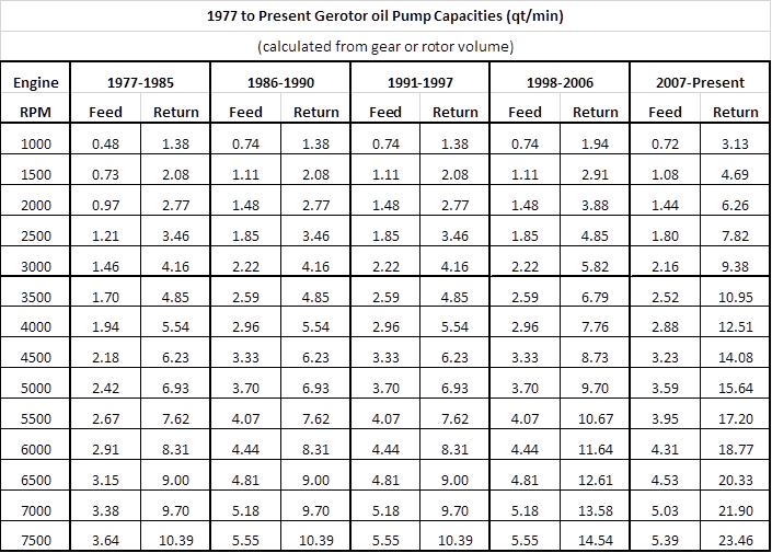
Below is a chart from testing done by Hippysmack showing the volume of oil delivered by the various gerotor pumps (1977-up).
Real world testing results were just a tad lower than the charted measurements. The initial results were quantified in gallons/minute.
The chart below was converted to quarts/minute. 4)