Table of Contents
REF: Engine Mechanicals - Sub-07N
Dyno testing using the timing plug location for an additional crankcase vent by aswracing
The following is to share some dyno testing by aswracing of using the timing plug location for an additional crankcase vent. 1)
First, a little background.
In the stock configuration, the crankcase vents through a pair of “umbrella” valves, which are essentially check valves.
There is a slight air inlet into the motor from a tiny hole near the umbrella. 2)
It acts as both an oil drain for anything that gets past the umbrella and an air intake to keep negative pressure from getting too high.
The pistons come down the first time and the crankcase air is expelled with the air being forced out through the umbrella valves.
But when the pistons go back up, the umbrella valves block the inflow of air, causing a slight vacuum in the crankcase.
The next time the pistons come down, crankcase pressure will return to atmospheric at BDC before the upstroke.
If no air is allowed into the motor, the crankcase will cycle between a vacuum (pistons up) and atmospheric (pistons down).
However, some air is actually allowed to enter, primarily in the form of blow-by that escapes the combustion chamber past the rings.
Therefore, in the stock design, there is a small net outflow.
The amount will vary with the condition of the motor.
Properly functioning umbrella valves therefore serve the purpose of significantly reducing the breather capacity requirement while also minimizing crankcase pressure.
Excessive airflow & oil discharge through the breathers can be caused by malfunctioning umbrella valves that are allowing more air into the motor.
For this test, an additional vent was added at the timing plug hole.
No check valve was installed on this vent.
Therefore, the crankcase is being allowed to pull in air as the pistons go up.
This fundamentally changes the engine's venting design.
Some people feel that allowing the engine to both inhale and exhale in this manner reduces crankcase pressure.
Several people cite a “seat of the pants” improvement in performance.
The purpose of this test was to determine if there actually is a performance improvement from this change to the venting system.
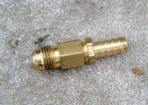
The fitting arrangement used is in the pic below.
The threads on the flare match the timing plug hole threads.
There are two fittings threaded together and app. two feet of 3/8“ I.D. hose was attached to the hose barb.
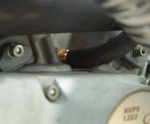
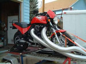
| 3/8” flare to 1/4“ FPT fitting with a 1/4” MPT to 3/8“ hose barb. 3) | Fitting and hose as installed on the bike.4) | Test bike (near stock 1999 M2). 5) |
 |  |  |
Lots and lots of dyno pulls were performed in each configuration and the configuration was switched back and forth a few times.
Dyno results are not 100% repeatable, and as such, below is a range of results for each configuration, as well as a comparison of best pulls.
Click on a chart to enlarge:
| 10 best pulls from the stock configuration. 6) | 10 best pulls from timing plug vent configuration. 7) | Best stock pull and the best timing plug vent pull. 8) |
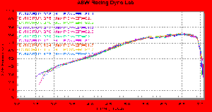 | 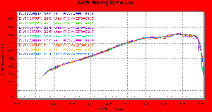 | 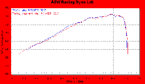 |
As you can see, the difference is within the repeatability of the measurement.
If a person *had* to declare a winner, the results with the stock setup would seem to have a little edge.
(both in the “best” results and just looking at the average of the 10 best results)
But I'd be careful doing that, you could be looking at normal variation.
Observations:
I was surprised at how little air movement there was at the end of the hose.
When a motor is started with nothing screwed into the timing plug, there's a massive inhalation and exhalation evident.
But apparently, necking it down to a 3/8” hole and connecting 2 feet of hose adds a pretty significant restriction.
Air flow was nowhere near what I expected.
Unfortunately, getting a 7/16“ or 1/2” hose into that area would be problematic, space is tight.
Plus, a fitting with the correct thread and a 7/16“ or 1/2” hole may not be available.
Another surprise was just how easy it was to plug the hose with my finger, and how it felt when I did.
The pressure was not great.
Regarding horsepower gains from different breathers
From aswracing on testing breather vents for HP gain: 9)
Many years ago, I spent most of a day dyno testing breather check valves.
I was writing for Battle2win magazine at the time and published my findings there.
The article is here at Nightrider.com: Do Crank Vents work?
I spent several hours on the dyno testing whether or not various breather arrangements affected the power of a motor. 10)
Mainly it was a test of these breather check valve devices, but I also tested the recycling of the blowby versus venting to the atmosphere.
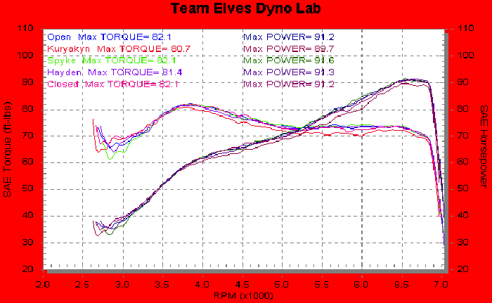
The result labeled “kuryakyn” is the one that's recycling the blowby.
So named because I used a kuryakyn adapter to send the blowby back into the intake tract.
All the others are vented to the atmosphere.
The bottom line was that none of them added a single iota of measurable horsepower, despite the grandiose claims of up to 7% from the manufacturers.
The only thing I could get to show up on the dyno at all was the removal of the blowby from the intake tract.
You can read all about the results in the Nightrider article above.
One of the companies involved, ET products (maker of the Spyke Krank vent) took exception.
I very carefully retested using their suggestions, but I got the exact same answer.

