Table of Contents
This is an old revision of the document!

REF: Engine Mechanicals - Sub-04E
Building Your Own Slack Tube (Manometer)
See also in the Sportsterpedia:
Building the Unit
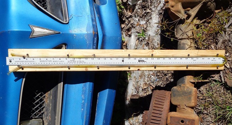
The slack tube below is made from 1/8“ clear Tygon vinyl tubing and a 2×4 app 3 feet long. 1)
The backing plate is a 2×4 with an aluminum 36” ruler attached with drywall screws.
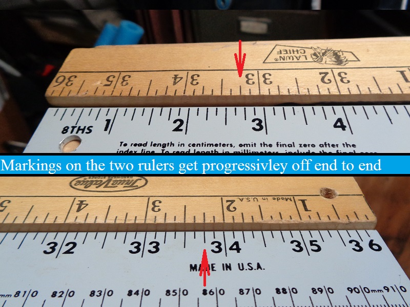
The two rulers below (right pic below) show the measurements on the wooden ruler to be 1/8“ longer than the steel one in a 36” run.
Ambient temps can also shrink or expand the ruler whether wooden or aluminum so that has to be taken into account of subsequent tests.
The drywall screws were also used to bind the hose between the ruler and the shank using the screw head to hold the hose down. 4)
The black connector at the top is a cut down spark plug boot used as a sleeve for the hose connections.
(technically if you buy enough length of hose, you don't need the connector)
Just make sure all connections are sealed good.
The engine will suck on the hose for the most part in varying degrees so there's not enough pressure to blow off the hose.
A small piece of plywood screwed to the bottom of the 2×4 makes a nice stand for the unit.
Then all you have to do is remove the timing plug, install the new fitting and hook the hose end to it.