This is an old revision of the document!

IH: Oiling & Lubrication - Sub-03Q
77-85 Oil Pump General Wear and Damage Issues
Below are some general wear issues as well as secondary issues that may affect the operation of the oil pump.
General wear is a given as all moving parts will eventually show an amount of wear.
Secondary damage or problems are sometimes not thought of and consist of other parts of or in the motor that may end up damaging the oil pump.
Note: Any time there is a question about the oiling system, FIRST MAKE SURE THERE IS OIL RETURNING TO THE OIL TANK.
If there is no oil returning, do not run the engine any longer until you've discovered why that is.
Seeing oil returning to the tank is usually a good thing. It verifies that the return side of the pump is working. 1)
(which verifies the drive gear that drives the shaft that drives both pumps is working)
On the old gear pumps, it is a pretty good indicator that oil is coming out, so oil must be going in.
But on the later gerotor pumps, 1977 onwards and with that big seal between the two halves of the pump, it ain't necessarily so.
If the seal between the supply and return pumps is leaking, the return pump is in effect sucking straight from the oil tank,
Via the supply pump and leaky seal and is not picking up any air from the sump. Return flow will look fantastic.
(better than on a properly functioning oil pump in fact!)
- Possible causes of low or no oil to the motor or oil tank (discussing the oil pump only):
- There have been reports of oil pump to case gaskets made with the feed hole punched out.
This would keep feed oil from entering the motor.
Always check that before installing the oil pump on the motor. - Cracked gerotors or too much clearance between the inner and outer gerotors will lower outlet pressure / oil flow to the motor.
The gerotors work by picking up oil from the inlet cavity and moving that oil to the outlet cavity.
As the gerotors turn, previous oil deposited in the outlet cavity is pressured to keep moving the next time the outlet cavity is filled on rotation.
If there is a crack in a gerotor or a wide clearance between inner and outer gerotors, pressure will be forced into these areas instead.
The crack may open up under pressure and let the oil out also.
Basically you lose some pressure on the outlet side as some oil is simply being transferred from the outlet side back to the inlet side of the pump. - An out of round gerotor bore in the housing or cover can reduce oil pressure.
This equates to too large of clearance around the gerotor OD lessening the hydraulic seal.
This can be caused by the separator plates and/or gerotors getting sideways in their bores and wearing the surrounding aluminum. - Air leakage into the pump can result in low oil pressure.
If oil can leak out, air can leak in. Just as the oil return in the tank can be seen in spurts, the feed side also comes in spurts.
So there is a small instance of high and low pressure coming from the feed gerotors to outlet pressure.
This can equate to a push / pull situation inside the oil pump (both having their own pressure cycles).
So the pump can leak oil out of cracks and a quick cycle of vacuum (or reverse pressure) can pull in air from the outside into the pump.- Loose hose clamps at the oil pump and/or oil tank feed hose fittings or split hoses can create air leaks.
If using crimped hose connectors, check them to make sure they are tight. If using worm drive hose clamps, make sure they are tight.
Also make sure they haven't been tightened too much (which can cut into the hose under the clamp).
This will prevent air leakage into the system which could cause loss of oil pressure due to an airlock in the oil pump.
Also periodically check all hoses for rot. - Cracks in the pump cover (big or small) at the area of the oil pressure switch are also a source for air intake.
When installing the oil pressure switch, make sure you don't tighten it too much.
5-7 ft/lb (or hand tight plus a nudge) is all it takes to tighten the pressure switch.
Much more than that will simply crack the aluminum around the threads.
Click Here to read more about the oil pressure switch in the Sportsterpedia. - The oil pump has to be primed or it will not pump oil.
If you've recently removed the oil pump or feed hose (drained the oil from), air will be present instead.
It takes a hydraulic seal around the gerotors to create oil flow/pressure.
There have been several reports of work done on the oil pump or an oil pump swap in where no oil flow was noticed during the first ride afterward.
Any time the oiling system is worked on, make sure to first check that there is return oil coming back into the oil tank.
(especially before risking a no oiling condition on the road)
Once the oil pump is initially primed, it should stay primed until such time the pump or feed hose is later removed.
- Sheared pin on the gearshaft that turns the gerotors:
There are two solid pins (1 for feed side, 1 for return side) on the gearshaft that are responsible for turning the gerotors.
Either pin can shear from wear or from a sudden jolt on the oil pump in operation.
If on return side, the return gerotors stop turning and oil backs up in the sump (wet sumping to follow).
Most if not all the oil in the tank will be pumped into the motor but you'll get no return to the tank.
If on the feed side, the oil light should come on (everybody SHOULD have one) to let you know oil is not feeding the motor.
The oil tank will stay full with no oil moving about.
If both pins shear at the same time…. you've probably already discovered more problems at that point. - If the oil lines are ran incorrect, this could stop the oil flow to the motor.
- If the oil pump check valve is blocked or seized in the closed position, you'll get no oil to the motor.
- General Wear / Damage Issues: (things to keep in the back of your head when dealing with oiling issues)
- Gerotors can crack but still work to a point.
That point may be where it finally wears out the pump housing to gerotor OD clearance thus delivering less oil to the motor.
There is no spec for gerotor to housing clearance.
But even hairline cracks in a gerotor will allow it to expand when hot.
This will eat away at the housing bore, heat up the pump and internals causing damage to other pump parts as well.
Cracked gerotors will also produce less oil pressure. - Gearshaft pins can shear off, stopping either the feed side or return side or even both from turning.
The solid pins in the side of the gearshaft are responsible for turning the gerotors.
The pins will wear and sometimes they will shear off. Each gerotor set has it's own pin.
So it's possible for the pin on the return side to shear with the pin on the feed side staying in tact or vice-versa.
So you could have feed oil to the motor but no oil return to the tank or vice-versa.
Always check for oil returning to the tank when diagnosing any suspected oiling issues (or any time after checking the oil for that matter).
Never check oil level without the motor being up to operating temp.
So before you shut the motor down to check the oil, have a look in the tank to verify that oil is returning.
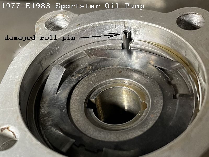
Damaged Pump Housing Roll Pin
A roll pin is a spring, that's what keeps it in place. It's not solid because it's NOT supposed to shear. 2)
The roll pin in the oil pump housing can be damaged (by the parts in the pump getting in a bind) or by a previous hamfisted pump assembly. The pin can also be punished by the divider plates enough to wallow the hole it's in and/or damaging the hole enough to loosen the pin. This may be due to foreign matter in the feed or return cavities. Or the pin can be damaged from trying to remove it.
The gerotors are already under pressure due to the spring washer design between the inner and outer divider plates.
The hole in the center of the divider plates is off center. The roll pin locates the plates.
The roll pin shouldn't see any shear force.
The scavenge gerotor is not quite as tall as the “shelf” where the inner plate sits.
Normally, there is a slight gap between the return gerotor set and the inner plate. Inner plate sits against the shelf, not the return gerotors.
When you button up the pump and the spring washer tightens the turning of the gearshaft, it's tightening against the feed gerotors, not return.
So the return side should be free to move up and down with RPM and float off the plate.
The plate, wanting to turn, would be considered shear force on the housing roll pin.
Any foreign objects that enter the pump can increase the pressure against the plates to move.
Any increased pressure may be enough to grab and spin the plate(s) hard enough to damage the pin or knock it out of it's hole in the housing and/or break the area of the hole for the pin. If the roll pin comes out, it will cause damage to the oil pump. If it gets lodged between the inner and outer gerotors, it'll most likely crack the outer piece (weaker of the two pieces). If it gets under the gerotors, it'll get dragged across the gerotor surface in the pump housing or cover. This will end up in scratches on the machined surface and lower oil pressure from the pump due to the scratches. With the roll pin out, the outer plate, under pressure, can spin and wallow out the feed bore in the housing around the plate.
Possible ways to remove the roll pin.
- You can try a side dike wire cutter and a little electrical freeze spray on the aluminum.
- You could try running a small tap into the roll pin to cut threads for a small screw, then screw the bolt into the center.
Once the bolt hits bottom of the hole, it may push the pin up and out or at least loosen the pin. 3) - You may or may not need to cut the buggered part off, but you could try to fill the pin with oil and insert a close fitting punch into the hole. The hit the punch with a hammer. The hammer blow may move the pin upward. 4)
- This is tedious but would work, if done properly and with a steady hand.
This method may also be used if the existing hole is broken out or the is wallowed to where a new pin would not tighten up to the existing hole. You could carefully cut the old pin flush with a Dremil tool, leave the old pin where it is and install a new pin elsewhere. Note: if you drill a new pin hole you must cut new slots in the 2 plates that the pin locates. 5) You can't rotate the plates into a different position because the hole in the plates that the shaft goes through is not exactly in the middle (off centered).- First, remove the guts inside and install both divider plates over the old pin to locate them properly. Then drill a small hole (smaller than the pin hole) thru the top plate, thru to the bottom plate and stop when it is dimpled by the drill bit. Remove the plates and finish drilling the second plate. Then use a Dremil tool or file to cut a slot from edge of plate to hole (on ea plate)
- Reinstall both plates and drill thru the new slots in both to make a dimple in the pump housing, remove plates.
- Drill hole in pump housing to depth of new pin (correct bore size for new pin).
It's good to have an index drill bit set (especially for smaller bits). Most drill bits will wallow a hole bigger than what it is written on the bit. Start with a slightly smaller bit than (projected installed OD of the pin dia) into the plates and just enough into the housing to make a dot. Then pull it back apart and square up the housing using the same drill bit. Measure it and drill with bigger bit if needed for the pin. If you drill too wide, the pin won't stay. Roll pins are sized by the dia of the hole needed (1/8“ roll pin for 1/8” hole) but the pin will measure bigger than that. Just need to make sure the hole doesn't wallow. - Use a metal cutting blade on a Dremil cutting tool to cut the old pin flush with the “shelf” in the pump housing. Make sure there are no splinters left on the existing pin (needs to be flush to the shelf it sits on) and the shelf has no gouges that would push on the divider plates when installed.
- Blow out the new hole with compressed air, press the new roll pin into the new hole and you're done.
Generally bad ideas for removing the pin.
- Vise Grips will most likely pull off the pin and damage it further, but more importantly damage the pump housing.
- Heat will most likely expand the aluminum around the pin, squeezing it harder around the pin.
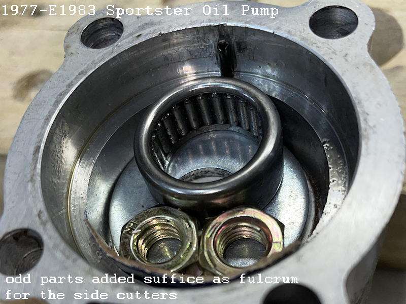
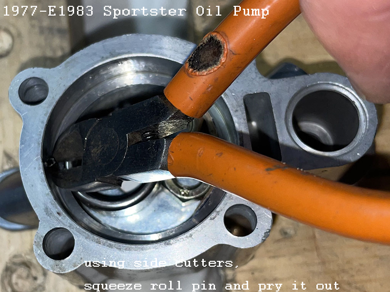
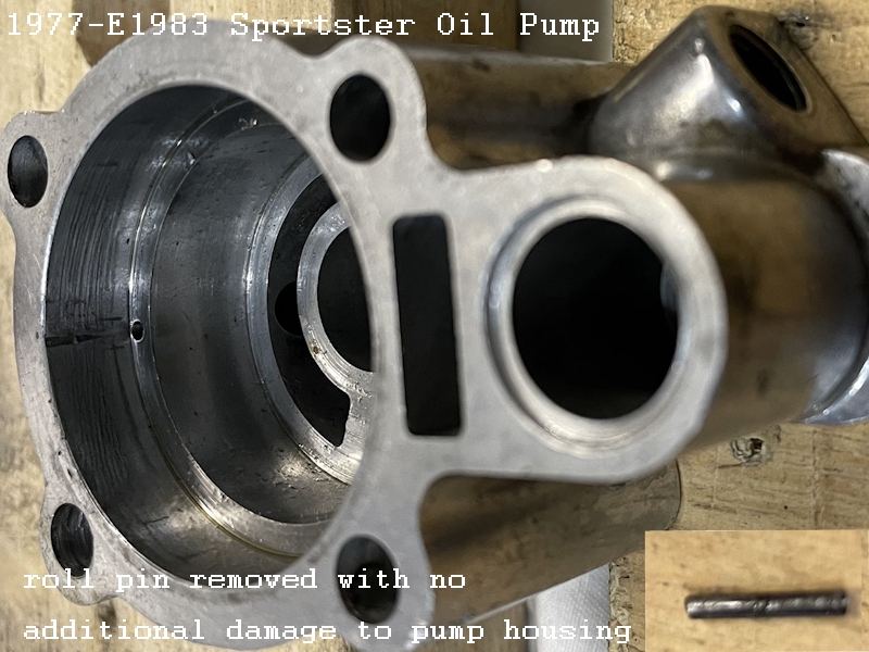
The roll pin below was removed using electrical side cutters by XLF member, billeuze. 6)
Carefully protect the base and sides of the pump body.
Odd parts were put inside the pump for a nice height for a fulcrum for the side cutters.
I squeezed and pried it out. It took 4 or five pries to walk it all the way out. ((photos by billeuze)