Table of Contents
This is an old revision of the document!

IH: Engine Mechanicals - Sub-01G
Ironhead Gearcase/Cam Cover Removal and Installation
Cam Cover Gasket
Click Here to read more about gearcase changes around the upper feed galley.
Make sure to use the correct gasket for your engine/cover specifics.
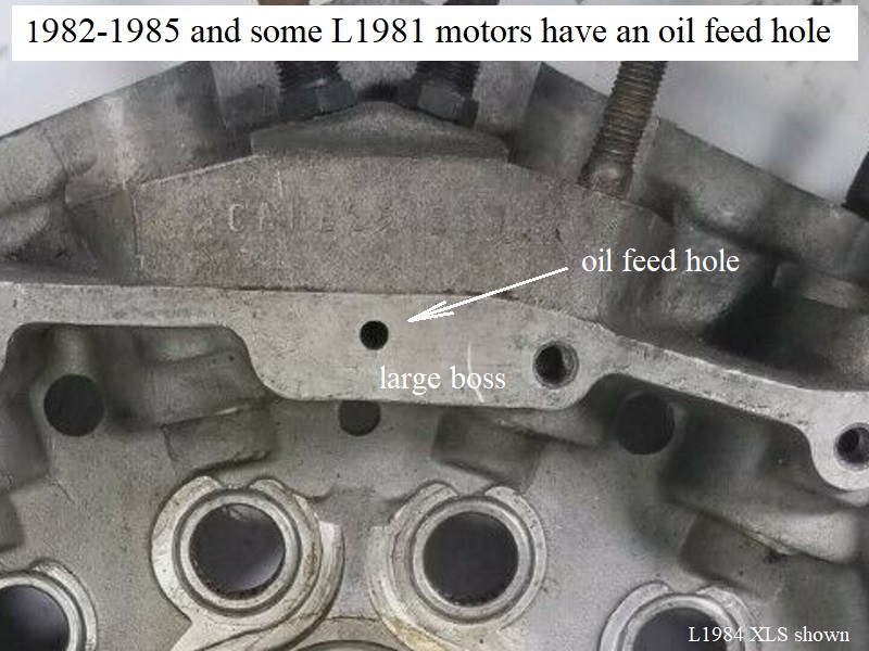
There were changes to the upper feed galley that dictate a specific gasket, especially between 1979-1982 models.
1957-E1982 right cases with the small boss and upper oil feed oil slot:
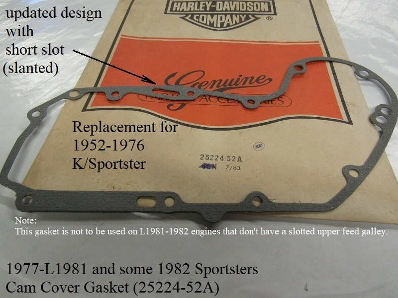
1952-1976 K and Sportsters original gasket (25224-52), designed with an upper feed oil hole. Updated gasket (25224-52A).
1977-L1981 and some E1982 Sportsters original gasket (25224-52A) original had a single for the upper feed galley passage.
The original gasket was updated in Nov. 1979 with a short slanted slot added to match the gearcase modification in L1979-E1980 models. 1)
And the updated -52A gasket replaced the -52 gasket for 1952-1976 models in the -78B catalog.
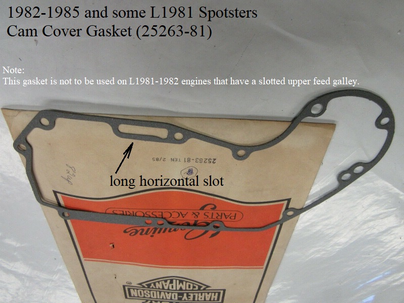
1982-1985 and some L1981 right cases with the large boss and upper oil feed hole:
L1981-1985 Sportsters use gasket (25263-81), designed with a long horizontal slot.

| Cam Cover Gasket (25224-52A) 4) | Cam Cover Gasket (25263-81) |
 |  |
Cam Cover Fastener List
Click Here to read “Finding Acceptable Lengths for Gearcase/Cam Cover Screws” in the REF section of the Sportsterpedia.
The fasteners for 1952-E1981 can be changed out to socket head screws to keep from having to deal with slotted, phillips or posidrive heads.
The list below shows factory screws and sizes.
Here is a link to Bolt Depot for their “Socket Flat Head” fasteners page (zinc, chrome, stainless or allow).
- 1952-1970 K/Sportster Cam Covers Use:
- (9) Cover Screws.
- 1/4“ x 20 x 1-1/2” Oval Slotted Head Bolt Screw (2345) x 3.
1/4“ x 20 x 2-5/16” Oval Slotted Head Screw (2353) x 5.
1/4“ x 20 x 2-1/4” Oval Slotted Head Screw (2352) x 1. - Colony replacement kit (8895-9)
- (2) Generator Mounting Bolts.
- 5/16“ x 24 Bolt (30013-52) x 2. Angled shank under head to sit flush in mounting hole.
- (2) Solid Dowel Pins.
- .308” dia x .690“ long (375). Gearcase has matching dowel pin holes in front and rear.
- 1971-1976 Sportster Cam Covers Use;
- (8) Cover Screws.
- 1/4” x 20 x 1-3/4“ (1971-1973 Phillips Head Screw, 1316W x 3) or (1974-1976: Posidriv Head Screw, 1316W x 3).
1/4” x 20 x 1-1/4“ (1971-1973 Phillips Head Screw, 1317W x 1) or (1974-1976 Posidriv Head Screw, 1317W x 1)
1/4” x 20 x 2-1/4“ (1971-1973 Phillips Head Screw, 1370W x 4) or (1974-1976 Posidriv Head Screw 1370W x 4)
- (2)- Generator Mounting Bolts
- 5/16” x 24 x 3-1/4“ Hex Head Bolt (30013-71) x 2.
- (2) Solid Dowel Pins.
- .308” dia x .690“ long (375) x 2. Gearcase has matching dowel pin holes in front and rear.
- 1977-E1981 covers use;
Note: screws for 1979 XLS were painted black, part#s were different for that fact.- (8) Cover Screws.
- 1/4” x 20 x 1-3/4“ Posidriv Head Screw, (1316W) x 3.
1/4” x 20 x 1-1/4“ Posidriv Head Screw, (1317W) x 1.
1/4” x 20 x 2-1/2“ Posidriv Head Screw (1381) x 4.
- (2)- Generator Mounting Bolts
- 5/16” x 24 x 3-1/4“ Hex Head Bolt (30013-71) x 2.
- (1) Solid Dowel Pin.
- .308” dia x .690“ long (375). Cover has hole for rear pin but gearcase doesn't. Pin is used in front of cam cover.
- L1981-E1984 covers use;
- (9)- 1/4” Cover Screws.
- (2)- Generator Mounting Bolts.
- 5/16“ x 24 x 3-1/4” Hex Head Bolt (30013-71) x 2.
- (1)- Solid Dowel Pin (375), .308“ dia x .690” long. Pin is used in front of cam cover.
- L1984-E1985 covers use;
- (9)- 1/4“ Cover Screws.
- (2)- Oil Filter Mount Bolts
- 5/16” x 18 x 3-1/4“ Hex Head Bolt (4392) x 2
- (2)- Solid Dowel Pins (375), .308” dia x .690“ long.
1 dowel pin is used in front on gearcase. 1 dowel pin is used in the right case, lower tranny area.
Torque Specs
Due to the early manuals NOT having torque specs for these screws, many developed a “torque stop” in their wrists and elbows.
However, in order to develop the “feel” for when to stop, you have to bend or break some screws first.
Do not try and stop a leak by tightening the screws any harder than you would installing them in the first place.
Click Here to read about, Using “Feel” While Tightening, on the torque wrench usage page in the Sportsterpedia.
Caution: Too much torque on fastener's can create a leak or make a leak worse than it is.
For those who would like a guide to proper torque on the screws, specs are below.
It's always a good idea to clean the screw threads and the threads in the aluminum case before using them.
Any dirt/oil debris in the threads WILL change the torque that you actually apply to the screws.
You should be able to run a screw in each hole in the gearcase before installing the cover and bottom it out by hand without any binding or hesitation.
If not, the threads need attention before proceeding.
If you can't blast the threads clean, Click Here to see the article in the Sportsterpedia on chasing threads with a tap or thread mender tool.
- Cam Cover Screws:
- 1957-1969 FSM: There are no torque specs or sequence for cam cover screws other than “tighten all screws evenly”.
- Snug plus a nudge is a general rule.
- Use 1970-1985 specs for best results (80-110 in/lbs).
- 1970-1985 FSMs:
- Tighten all cam cover screws to 80-110 in/lbs evenly.
- Generator Bolts (1957-E1984): 1957-E1984 FSMs have no reference to generator bolt torque.
- Snug plus a nudge is the general rule.
- 70-85 FSM makes no distinction between cover mounting screws and generator mounting bolts.
- Oil Filter Housing (L1984-1985):
- Tighten bolts to 13-16 ft/lbs
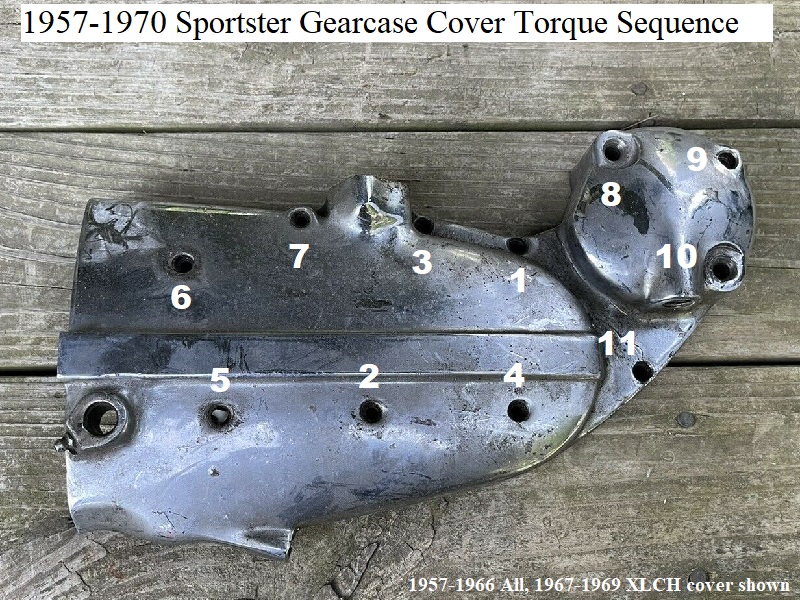
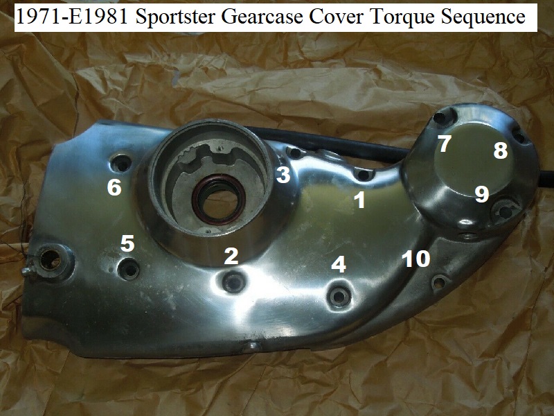
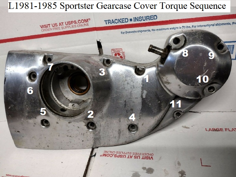
Torque Sequence
The only sequence for tightening the cam cover screws in Ironhead manuals is “tighten all screws evenly working opposite from one another”.
That's basically referring to what is commonly known as a “cross pattern”. Trouble is, the screws are not all in the position to accept a cross pattern.
Some are on the sides and corners and you can mess this up tightening the wrong ones first or last.
Tightening one screw effectively loosens other screws so the process is still a little wanting from the manuals.
It wasn't until 1992 that the MoCo included an illustration in the FSM showing the sequence to use for torque on these bolts.
It is a cross pattern in the middle and following side to top screws in pattern and this same sequence can be used on 1957-1991 model cam covers.
Since getting all the screws evenly tightened has always been the goal, the 92 torque sequence can't hurt if you'd like to use it.
This will help keep you from snapping screws, cracking the case or creating oil leaks.
Don't try to get to the torque spec all at once. Divide the intended torque into steps using at least 2 full passes (3 is better).
It's a small torque spec but even torque on all screws is the goal, not the spec.
Click Here to see the torque wrench page.
On the right menu, click on “Using a Torque Wrench” scroll down to Technique.
It's safer to use a beam type wrench on these fasteners than a clicker type wrench.
| Beam type in/lb torque wrench w/ hex adapter 5) |
 |
Below are pics with the adapted sequence shown. Use at your own discrepancy.
 6)
6)  7)
7)  8)
8)
Installing the Cover
Easiest way to install the cover is to cut a few pieces of threaded rod about 3-1/2” long (or cut heads off long 1/4“ screws/bolts) for cover “holders”.
Insert a rod by hand into two or three mounting holes turning to get several threads in (it doesn't have to get tight).
Install the cover gasket and cover over the rods and push lightly on the cover to take up any space to the gearcase.
The rods help the cover come up evenly without binding anything.
Install several mounting screws in unused holes to “just snug” then remove all the rods and install all the other mounting screws “just snug”.
Then use the torque specs and torque sequence above.