Table of Contents

IH: Electrical System - Sub-02A
Bench Testing a Generator
Article by sifty of the XLFORUM 1)
Some simple diagnostic tests can be done with a multimeter.
Note, these tests should be performed after the initial visual inspection and cleaning as outlined in the service manuals.
And so are based on testing the unit out of the bike.
The results of these tests should determine if anything is seriously wrong.
But will not identify an intermittent generator fault,
(these can be hard to diagnose, and probably need testing on the bike so the genny can be driven at varying revs).
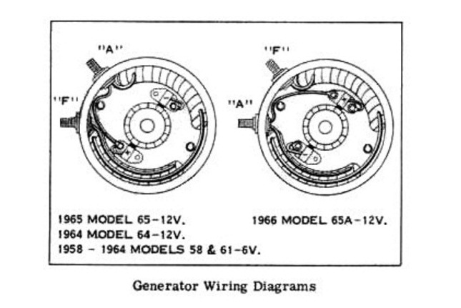
- Generators are fairly simple, they consist of; 2)
- Field windings are designated “F” (attached to the case).
- Armature windings are designated as “A” (wound around the rotating shaft).
- And spring loaded brushes which connect to the commutator section of the armature.
- Most generators will be the 65 or 65A type.
- You can identify the “A” terminal (if not marked) by seeing which one goes to both a field winding and one of the brushes.
- Note this brush must be insulated from the brush plate, while the other brush is not as it is the negative part of the 12V circuit.
So is directly connected to ground. - Generally if the windings test out ok, the generator should operate correctly;
- There are no short circuits.
- And the commutator, brushes and bearings are clean and in good order.
Brush assembly
 The brush plate is easily removable, and inspection/ cleanup should be straight forward. 3)
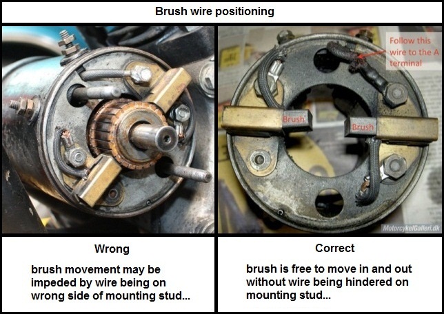
Care must be taken when installing the brush plate.
Make sure that the brush- armature connecting wire is not pinched (can short circuit to the frame).
And also that it is routed around the long mounting bolt and has enough length to not hinder installation.
(the plate has a locating pin and can only be installed in one position)
The brushes must be free to move when installed.
Ensure the connecting wires are tightened in a position to allow full movement.
And make sure the bare end of the armature brush wire does not contact the case or end cap on assembly.
Terminal insulation
The terminals must be insulated between where they go through the case and connect to the windings.
There will be some sort of fiber or plastic bushing around them at this point.
These can crack or lose their insulating properties through a build up of dust/oil/ grime.
A good cleaning may restore things.
But you can make new plastic bushes to replace the decades old fibre/plastic ones that are beyond salvage.
The winding insulation test below will indicate the status of this insulation.
Armature
Testing on the Ohms scale between each commutator segment and the exposed iron core will indicate any short circuits to ground.
Each segment should show very high resistance to ground (ideally in the Mega-ohms range).
You can also test between adjacent segments for continuity (this reading should be very low) in the 0.1 ohm sort of range.
Make sure you do not damage the soft copper of the commutator with the pointy test leads when carrying out these tests.
The the armature is where most problems should occur and these tests are very rudimentary.
But rule out obvious issues to begin with.
Simple Generator tests
With the generator cleaned, assembled and on the bench, some simple test with the multimeter in the Ohms scale can tell you a lot about its electrical health.
The figures noted here were the results from 2 generators (different models).
They should be reasonably typical the standard 12V Harley generator. 4)
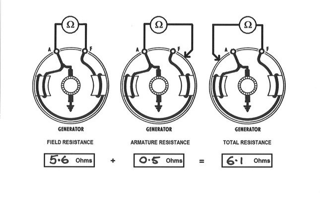 Field winding resistance:
Placing the leads across the A and F terminals will give you the effective resistance of the field windings (2 windings in series).
The armature circuit is not included as in a healthy generator there is no return path via ground to the meter.
This should be around the 5.8 ohm mark, a higher figure indicates a possible open circuit, and a lower figure may mean a winding is shorting out somewhere.
Armature resistance:
Placing one lead on a good, clean ground point on the case (shiny metal) and the other on the A terminal, will follow the path through the armature to ground.
This should be very low, typically less than 0.6 ohms but can vary as it depends on the brush/commutator condition.
Total resistance:
Placing the leads on a good ground point and the F terminal effectively measures the field plus armature circuits in series (from the F terminal, through the field windings, then through the armature to ground).
As a quick check, this result should be very close to the values of the previous tests added together.
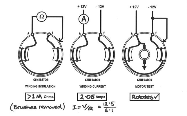 With the brushes out there are a couple of further tests available: 5)
Winding insulation:
Placing one lead on a clean ground point of the casing, and the other on either terminal (do both) should give a very high reading (ideally in the Mega-ohms range).
This indicates the windings are not shorting to ground anywhere.
Winding current:
Connecting the battery through the multimeter in the Amps scale should result in a DC current of around 2 amps.
Ohms law states V = IR, so with 12V and a resistance of around 6 ohms I = V/R which gives the 2 amps (will vary in practice as your winding resistance and battery voltage will differ).
Motor test:
This is probably the best indication, as a generator that will motor with voltage applied indicates all is well with the commutator / brush assembly.
Jumper leads from a good battery were used and a short piece of wire (applied +12V to the A terminal, and -12V to the case and F terminal simultaneously).
The generator was immobilized in a bench vise (between blocks of wood) for this test.
It should rotate quietly and smoothly, with no sparks apart from when you make the connection.
If it motors nicely there should be no reason the unit will not generate when spun.
There are other tests available with the generator on the bike.
(open field voltage, closed field voltage, current tests, all detailed in the manuals)
But if the above tests go OK,
A simple voltage test with the bike running should (hopefully) show around 15V at the A terminal to ground above idle speed, and you are away and riding…