Table of Contents

IH: Oiling & Lubrication - Sub-03U
XR-750 Oil Pump - Parts Lists and Information
1970-1987 racing pumps ran 1/4 speed of engine RPM.
The 1/4 speed gears on the both the breather shaft and pinion shaft were cut at a taller angle than on street motors.
Below is a pic showing the difference in teeth angles.

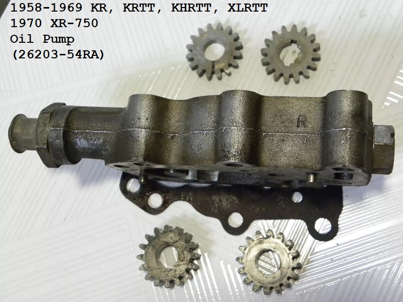
1970 XR-750 Oil Pump
Also used on 1958-1968 KR-750, KRTT,XLR 900 and XLRTT engines.
- Pump Speed is 1/4 of the engine RPM.
- Oil Pump Pressure as measured hot (140°F) at 5000 RPM, Max 10 PSI 2)
- Gear Dims:
- Number of Teeth: (16T)
- Feed Gears: O.D. (1.115“) - Width (.185”) - I.D. (.422“)
- Return Gears: O.D. (1.115”) - Width (.343“)- I.D. (.422”)
- Markings/Stampings: 26215-52 cast into the oil switch pad on the return side and the letter “R” stamped into the body, right rear outer side.
- Breather Timing: Timed off front cylinder. Opens 16°-20° (ATDC) and Closes at 80°-85° (BDC). 3)
- No oil pump pressure switch was used and the switch hole was blocked off by a 1/8” NPT x socket head pipe plug.
Special thanks to the The French Owl for providing period specific parts catalogs.
Parts List:4) 5)
 |
|||||||||
|---|---|---|---|---|---|---|---|---|---|
| Oil Pump Assembly | Oil Pump Body | Upper Cover / Breather Tower | Lower Cover Plate | Oil Pump Drive Gear | Feed Gear (driver) | Feed Gear (idler) | Return Gear (driver) | Return Gear (idler) | Idler Gear Shaft |
| 26203-54RA | 26217-58R | 26241-54R | 26250-56 | 26318-54R | 26323-52 | 26322-52 | 26320-56R | 26326-52 | 26327-52 |
| Breather Gear | Feed Gear Lock Pin | Return Gear Woodruff Key | Breather Shaft Ret Ring | Oil Pump Check Ball (3/8“) | Oil Pump Check Spring | Oil Pump Switch Nipple | Oil Switch Nipple Plug | ||
| 26331-56R | 603 | 26347-15 | 11002 | 8866 | 26364-57 | 26420-57 | 45830-48 | ||
| Feed Bypass Ball (3/8”) | Feed Bypass Spring | Feed Bypass Plug Rear Fitting | Pump Gasket Lower | Pump Gasket Upper | Pump Gasket Mounting | ||||
| 8866 | 26374-53R | 26423-52R | 26258-52 | 26259-52 | 26256-52 | ||||

Pics: click on any pic to enlarge. 6)


1972-1974 XR-750 Oil Pump
- Pump speed is 1/4 of the engine speed.
- Return gears operate at a 2:1 ratio of the feed gears.
- Gear Dims:
- Number of Teeth: (16T)
- Feed Gears: O.D. (1.115“) - Width (.185”) - I.D. (.422“)
- Return Gears: O.D. (1.115”) - Width (.370)- I.D. (.422“)
- The crankcase breathing system was used to return oil from the crankcase into the cam / gear cover using the timed breather valve gear.
From there, the oil drained directly onto the return gears of the oil pump. 7)- Breather Timing (standard): Valve opens at (14°-16° ATDC) front cylinder. Valve closes at (85°-90° ABDC) front cylinder.
Adjust breather timing by adding shims behind oil pump drive gear (on pinion shaft) and by increasing slot width in breather. - Breather Timing (improved): Valve opens at (5° ATDC) front cylinder. Valve closes at (105° ABDC) front cylinder.
Slot in upper cover must be widened to app .340” to make this possible.
- The motor is no longer fed only a portion of the pump's full capacity of oil as the bypass system of previous year pumps has been deleted.
Coincidently, the return gears are bigger to allow more oil to be scavenged from the motor.
There is a desceprency between the 1972 and 1975 parts books in where the upper and pump mounting gaskets are switched between the 2 catalogs.
Special thanks to the The French Owl for providing period specific parts catalogs.
Parts List is for XR and XRTT models: 8) 9) 10)
|
|||||||||
|---|---|---|---|---|---|---|---|---|---|
| Oil Pump Assembly | Oil Pump Body | Upper Cover / Breather Tower | Lower Cover Plate | Oil Pump Drive Gear | Feed Gear (driver) | Feed Gear (idler) | Return Gear (driver) | Return Gear (idler) | Idler Gear Shaft |
| 26203-54RB | 26217-72R | 26241-54R | 26250-56 | 26318-54R | 26323-52 26323-52A* | 26322-52 26322-52A* | 26320-72R | 26317-72 26317-72A* | 26327-52 |
| Breather Gear | Feed Gear Lock Pin | Return Gear Woodruff Key | Breather Shaft Split Ret Washer | Oil Pump Check Ball (3/8“) | Oil Pump Check Spring | Oil Pump Switch Nipple | Oil Switch Nipple Plug | ||
| 26331-72R | 603 | 26347-15 26340-36* | 26341-37 | 8866 | 26364-57 | 26420-57 | 45830-48 | ||
| Pump Gasket Lower | Pump Gasket Upper | Pump Gasket Mounting | Oil Seal | ||||||
| 26258-52 | 26256-72R | 26259-72R | 26227-58 | ||||||
* Parts updated through the 1975 XR-750 Parts Catalog.
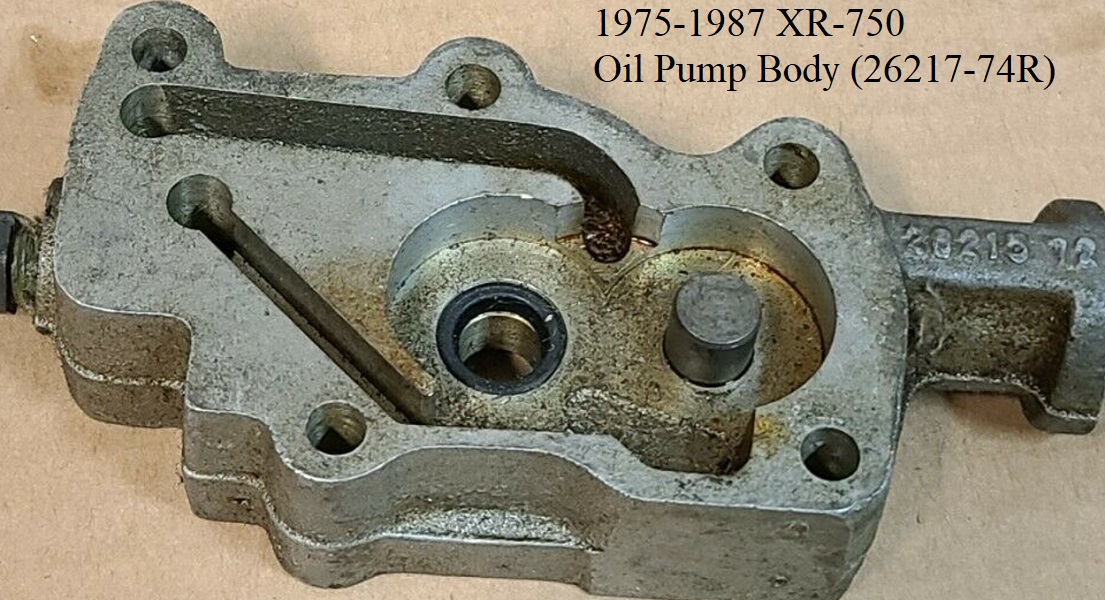
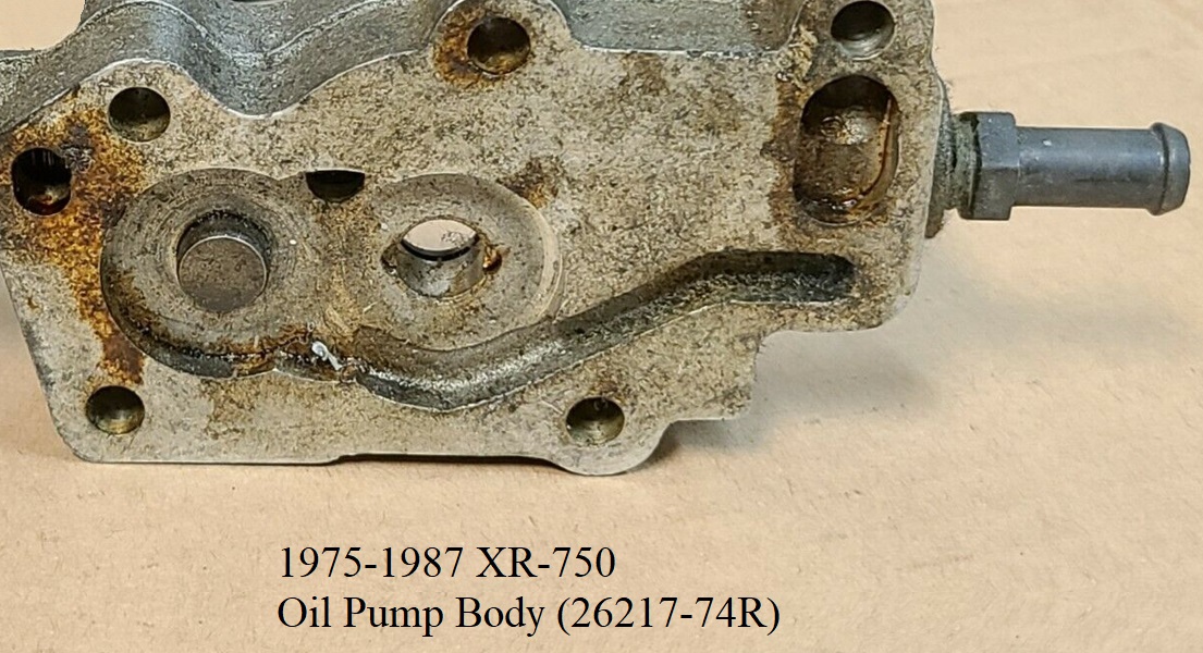
1975-1987 XR-750 Oil Pump
- Pump speed is 1/4 of the engine speed.
- Return gears operate at a 2:1 ratio of the feed gears.
- Gear Dims:
- Number of Teeth: (16T)
- Feed Gears: O.D. (1.115”) - Width (.185“) - I.D. (.422”)
- Return Gears: O.D. (1.115“) - Width (.370)- I.D. (.422”)
- Markings/Stampings: 26215-72 cast into the oil switch pad on the return side. No “R” stamped into the body.
- Breather valve has been undercut and is not equipped with a timing mark nor the tower with a timing slot. 1975 right case was designed with 2 holes in the cam wall to the gearcase. The crankcase breathes out to and in from the gearcase through those 2 holes as well as the breather gear. Breather gear is not used for primary air and oil removal as in previous years but as a way to add oil / oil mist to the cam gears. 11)
- Timing: Breather timing cannot be set on these engines.
- Engine got a bolt-on oil sump and windage tray. The additional sump has oil line fittings to accomodate incoming head drains / cam chest drain and outgoing sump oil to pump hoses.
- Return gears scavenge crankcase oil from the sump through an external oil line in the rear of the pump. 12) The internal scavenge hole from the pump to the cam chest reservoir was deleted. This allows full return pump vacuum to pull from the sump outlet through the oil nipple on the rear of the pump into a machined slot from there to the return inlet side of the gears.
Special thanks to the The French Owl for providing period specific parts catalogs.
Parts List: 13) 14) 15) 16) 17)
|
|||||||||
|---|---|---|---|---|---|---|---|---|---|
| Oil Pump Assembly | Oil Pump Body | Upper Cover / Breather Tower | Lower Cover Plate | Oil Pump Drive Gear | Feed Gear (driver) | Feed Gear (idler) | Return Gear (driver) | Return Gear (idler) | Idler Gear Shaft |
| 26203-74R | 26217-74R | 26241-74R | 26250-56 | 26318-54R | 26323-52A | 26322-52A | 26320-72R | 26317-72A | 26327-52 |
| Breather Gear | Feed Gear Lock Pin | Return Gear Woodruff Key | Breather Shaft Split Ret Washer | Oil Pump Check Ball (3/8“) | Oil Pump Check Spring | Oil Pump Switch Nipple Plug | Steel Oil Hose Fitting (3/8”) | ||
| 26331-74R | 603 | 26340-36 | 26341-37 | 8866 8873* | 26364-57 | 26420-74r | 63533-41 | ||
| Pump Gasket Lower | Pump Gasket Upper | Pump Gasket Mounting | Oil Seal (2) | ||||||
| 26258-52 | 26256-72R | 26259-72R | 26227-58 | ||||||
* Part updated through the 1972-1989 XR-750 Parts catalog.


1988-up XR-750 Oil Pump
- Pump speed is 1/2 of engine speed.
- Return to feed ratio is 4:1.
- Oil pump drive gear was re-activated as a breather only. Design same as 1975-1980 but with a more efficient gear design and improved oil routing.
- Breather timing: Turn rear piston to T.D.C. and line up 0.12“ dia. hole in gear shaft with notch in breather sleeve.
- Interchangability: To fit this oil pump to older engines (1975-1980 XR);
Modify sleeve (PN 26229-88R) by machining a 45° angle on lower shoulder to fit crankcase chamfer.
OR, machine a counterbore in crankcase to accept shoulder.
Depending on what type of frame is used, modification of lower right frame tube might be required.
This pump operates at 1/2 engine speed and requires drive gear (26213-83R) to be mounted on pinion shaft.
|
|||||||||
|---|---|---|---|---|---|---|---|---|---|
| Oil Pump Assembly | Oil Pump Body | Upper Cover / Breather Tower | Lower Cover Plate | Oil Pump Drive Gear | Feed Gear (driver) | Feed Gear (idler) | Return Gear (driver) | Return Gear (idler) | Idler Gear Shaft |
| 26203-88R | 26217-88R | 26228-88R | 26250-88R | 26316-83R | 26323-88R | 26322-88R | 26320-88R | 26317-88R | 26327-88R |
| Breather Gear Shaft | Breather Sleeve | Feed Gear Lock Pin | Return Gear Woodruff Key | Breather Shaft Split Ret Washer | Oil Pump Check Ball (3/8”) | Oil Pump Check Spring | Check Ball Plug | Lower Cover Pipe Plug (2) 1/4“ | Return Inlet Fitting (3/8”) |
| 26331-88R | 26229-88R | 637R | 26340-36 | 26341-37 | 8873 | 26364-72 | 26420-74R | 721 | 32463-88R |
| Pipe Plug (1/8“) | Return Outlet Fitting (1/4”) 1988 | Return Outlet Fitting (1/4“) 1989-up | Feed Inlet Fitting (1/8”) | Oil Seal (2) | Upper Cover O-ring (2) | ||||
| 45830-48 | 62570-83 | 25259-93A | 63541-74R | 26227-58 | 11159 | ||||
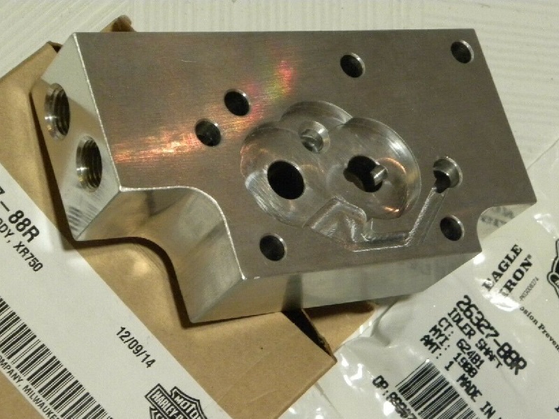
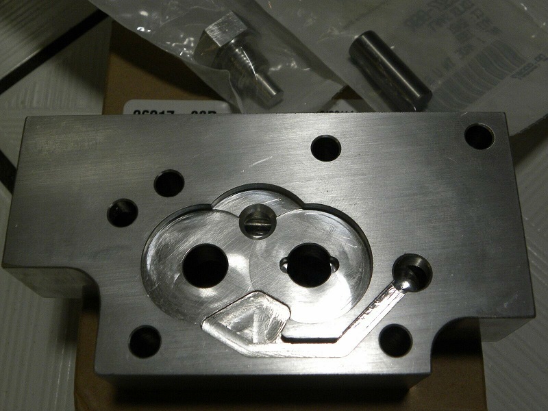
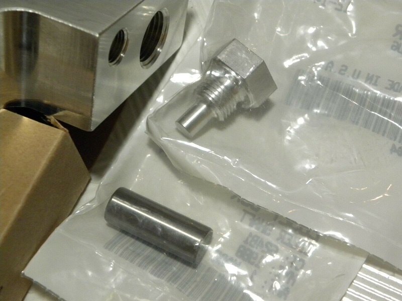
Pump Body 26217-88R
This is just the body without upper and lower covers. 24)


This is a used pump showing the covers and gears. 25)
The left side of this pump has 5/8“ dia. fitting for scavenging the sump and the 3/8” dia. for oil supply from the tank. The right side of the pump has ball/spring check valve and 3/8“ dia. oil return line to tank. The front side of the pump body has NPT plugs to block off passages from manufacturing/machining oil galleys. Can't make this pump any smaller and no reason to make it bigger, adding weight. Also the pump sits very close to the right side lower frame tube with very little clearance.
![]()
![]()
![]()
![]()
![]()
Feed Bypass System
1958-1968 KR, KRTT, KHRTT, XLR, XLRTT and 1970 Iron XR-750 Pump
All these models use oil pump body (26217-58R) which is machined with an internal feed bypass system to lower oil flow to the motor.
The bypass returns a portion of feed oil internally to the return gears.
How it's plumbed:
- The pump body has a vertical (bypass) hole drilled all the way through the pump body at app 11:00 from the rear outer mounting bolt looking at the feed side. On the return side of the pump, a “J” slot is milled from that hole around to the suction chamber in front of the return gears. A horizontal hole is drilled from the rear of the pump thru the vertical bypass hole and to the feed output passage in the pump. The horizontal hole is counter drilled in the rear for a ball stop near the vertical bypass hole. A spring and plug on the rear of the pump keeps the ball pressed against it's seat, closing off the vertical hole with spring pressure. The breather tower plate is not drilled for the bypass hole and closes off the top of that hole as assembled. So bypassed oil on these models gets sent to the bottom of that hole to the oil tank straight from the return pump's outgoing oil channel.
How it works:
- Feed oil is split where a portion of oil is fed to the engine and a portion of oil is internally sent to the return pump to be scavenged back to the oil tank from there. Oil that runs the horizontal bypass hole leaves the feed gears and pushes against the rear ball, pushing it backwards opening a path to the vertical hole. Lower oil pressure allows less oil to flow and higher pressure allows more oil to flow down the vertical bypass hole, through the milled “J” slot and into the suction chamber of the return gears. The gears send the oil to the return pressure side chamber, through the pump's return channel, into the engine return passage and out to the oil tank. The spring determines the output oil pressure to the feed side of the motor. The more oil that is bypassed, the lower the pressure of oil that enters the motor.
Rendering the bypass inoperable:
Since these pumps are for competition only, it is counter productive to block the bypass system.