Table of Contents

IH: Engine Control
Factory Ignitions
Battery Ignition (Circuit Breaker/Points/Timer/Distributor)
* . . . See more on the Circuit Breaker Ignition System
57-78 Sportsters (except 58-69 XLC and XLCH)
- The circuit breaker ignition system has two circuits; (1)-the primary and (2)-the secondary circuits. 1)
- The primary circuit includes the battery, switch, primary coil and the breaker points.
- The secondary circuit consists of the secondary coil and the spark plugs.
- The breaker cam and contact points open and close the low tension circuit between the battery and the ignition coil.
(which causes the coil to produce high voltage discharge to the spark plugs) - The circuit breaker also times the discharge for proper engine firing.
PRECAUTION: If the engine happens to stop on the 'dwell' part of the cam position lobe, the GROUND thru points will keep power active on the coil if the RUN switch is ON. This means, if you turned the key on (or leave it on), with the RUN switch ON, without starting the engine, the coil will be in constant current saturation and will eventually 'burn up' the internal windings.

(Aftermarket Points/Condenser Kit MC-DR2240X is typical for 71-78 models)
Magneto Ignition System
* . . . See more on the Magneto Ignition System
(58-59 XLC and 58-69 XLCH) 3) 4)
The magneto produces a high voltage discharge to the spark plug which is timed to each cylinder's compression stroke.
It also eliminated the need for a battery for ignition. 5) as you can kick start or bump start the bike at about 2-1/2 MPH or less. 6)
- Components include a single induction coil, a rotating magnet (rotor), a condenser, a circuit breaker and a circuit breaker cam. 7)
- Ignition is timed when the front cylinder piston is 11/16“ / (45° of crankshaft rotation) before TDC on the compression stroke.
Upon setting the proper timing adjustments at the factory;
Timing alignment marks were stamped on the drive housing plate and rear edges of the magneto adapter plate for future timing adjustments. 8) - A grounding circuit is connected to a button on the right handlebar (stop switch) that breaks the circuit to the ignition and stops the engine.
- Magneto mount changes:
- (1958-1964) Magneto is mounted in a fixed position producing advanced spark timing only.
- (1965-1968) Magneto is mounted on a movable plate allowing for spark timing retard.
Prestolite Electronic Ignition System
* . . . See more on the Prestolite Ignition System
(1979) Upgrade to the breaker point system in which the mechanical points are replaced by a breaker-less electronic ignition on the camshaft. Timer has a rotor with one small lobe and one large lobe and a sensor that sends signal to the control module on the back of the timer inner cover. Rotor is mounted on a mechanical flywheel centrifugal advance like a point cam would be in a breaker point system. The rotor's small lobe fires the front cylinder and the large lobe fires the rear cylinder. 9)1979 Ignition Module Assembly part number 32598-78 10).
Magnavox Electronic Ignition Systems
* . . . See more on the Magnavox Ignition System
- (1980 to 2003) Components include a timing rotor (timing cup), sensor plate or inductive pickup, ignition control module, ignition coil and spark plugs. For electronic advance, the inductive pickup generates TDC pulses that are sent to the solid state Ignition Control Module (ICM). The ICM computes ignition timing advance and coil dwell. In 1983, a Vacuum-Operated Electric Switch (VOES) was added to switch between 2 different spark advance curves built into the ICM. 11)
- This uses a Dual-Fire Spark system, using only one coil trigger wire to produce a spark on both plugs at the same time. (See coil information)
- The spark advance start point can be altered by physically moving the sensor plate in the “nosecone”.
Ignition Module - Timeout
From the manual:
| On 1980 and 1981 models, the solid-state ignition control module is mounted on the bottom of the battery carrier/oil tank. On 1982 and later models, the control module is located behind the side cover, mounted to the frame next to the battery. NOTE: On 1980-early and 1981 models, the control module shuts off current to the ignition coil 4 seconds after the ignition switch is turned ON. If the engine is not started within that time, the module must be reset by turning the ignition switch OFF and ON again. Later ignition modules allow 6 seconds for the engine to be started. The timing sensor is triggered by the leading and trailing edges of the 2 rotor lobes [Cam Position Sensor]. As rpm increases, the control module “steps” the timing in 3 stages of advance. |
The Coil is powered by the same WHITE wire as the Ignition Module. The Coil does not have power turned off by the Ignition Module, it simply, internally, stops GROUNDING the trigger side of the coil after 4 or 6 seconds in order to prevent burning up the coil (see the Precaution in the Circuit Breaker/Points section above).
NOTE: The RUN Switch does permit or kill the power to both the Ignition Module and the Coil - This means that in addition to the Keyswitch being able to reset the Ignition Module, you can simply flip the RUN Switch OFF & ON to RESET the module because that will completely power down the module & coil.
| Electronic Ignition Modules - All Models | |
|---|---|
| Year | Part No |
| 1979 | 32592-78 |
| 1980-1982 | 32399-84A* |
| 1983-1985 | 32436-91B* |
| * means P/N is retroactive from later model | |
Engine Control Related Components
Sub-Documents
VOES - Vacuum-Operated Electric Switch
- The computerized, microprocessor ignition module is programmed with two spark advance curves to meet varying engine loads. The system includes a vacuum operated electric switch (VOES). 12)
- The ignition module selects the proper curve when it receives an open or closed electrical signal from the VOES. This system ensures correct timing to suit starting, low speeds and highway speeds. 13)
- The VOES was first installed on Sportsters in 1983 (and used on most models thru 2013). The unit senses intake manifold vacuum through an opening in the carburetor body via a vacuum hose and requests from the Ignition Control Module switches between one of two different spark advance curves. The switch is closed at high vacuum operation (low engine load), utilizing a more advanced spark curve and it is open at low vacuum operation (high engine load), utilizing a less advanced (retarded) spark curve to minimize engine knock and still maintain performance. The VOES is installed above the intake manifold. 14)
- The high vacuum curve selected for maximum spark advance under normal light load conditions provides improved fuel economy and performance.
- The low vacuum curve (retarded spark) minimizes spark knock, while maintaining performance under high load conditions.
Spark Coil
Coil Mix-up on 1973-1974 Models
- Through an error with HD suppliers, an unknown quantity of ignition coils (31609-65A) were mislabeled as 12V coils but were actually 6V coils which possibly affected some 1973-1974 FL, FLH, FX, FXE, XL, XLCH and GE models. To prevent failed coils and poor ignition troubles, the MoCo suggested the dealers test all of their stock supply and all 1973 and 1974 motorcycles (in for servicing) that were suspect of having ignition problems. 15)
- With the wiring disconnected from the coil,
12V coil should have 5.00-5.50 ohms.
6V coil should have 1.25-1.45 ohms.
Failed Coils on 1980 Models
- A quantity of ignition coils (31609-80) used on all 1980 models, failed at low mileage. The problem was an internal breakdown of the windings within the coil. This is a failure that could lead to poor vehicle performance and a possible fouled spark plug. 16)
- Upon inspection of an ignition related failure, follow the diagnostic procedure outlined in the service manual. Inspect the primary and secondary coil resistance with an ohmmeter.
- Resistances should be:
- Primary: 3.3-3.7 Ohms
- Secondary: 16500-19500 Ohms
| Ignition Coils - All Models | |
|---|---|
| Year | Part No |
| 1980-1984 | 31609-80 |
| 1985 | 31614-83A |
Spark Plugs
The HD plug number corresponds to the recommended heat range of the plug.
HD 4 represents a spark plug with a heat range number of “4”.
HD 5 is a hotter plug than HD 4.
HD 3 is a colder plug than HD 4.
| Year Model | HD Plug Recommendations | Gap | Size |
|---|---|---|---|
| 1957-1978 17) 18) Mechanical ign | HD 4 (engine break-in) HD 5 (normal hwy to hard service use) | Magneto Ign .020” Battery Ign .025“-.030” | 14mm |
| 1979 19) Presolite electronic ign | HD 4 → HD 4R5 - resister type → | .060“ .038”-.043“ | 14mm |
| 1980-1985 20) Magnavox electronic ign | HD 4-5 → HD 4R5 - resistor type → | .038”-.043“ | 14mm |
Timing
Sub-Documents
* . . . Why timing advance changed from 45°- 40° in 1972 (commentary from Dr Dick)
Ignition Timing and Related Specs
- Ignition timing is when the spark takes place - specifically as the piston is traveling UP on the COMPRESSION stroke (compressing the gasses so that you get the most out of the explosion/ignition). 21)
- Top Dead Center is when the piston is at the VERY top of its travel, in the center of it's dwell area, and is usually referenced to mean on TDC of the COMPRESSION stroke (with the valves closed and the mixture compressed), though the piston will also be at TDC on the Exhaust stroke when the flywheel turns one complete rotation in either direction from TDC of compression. 22) So, the piston will be at TDC twice per 1 full revolution of the cams. Timing is measured (and set) from TDC on the compression stroke. See more on Finding TDC on Compression Stroke in the Sportsterpedia.
- Spark ADVANCE - is how soon, BEFORE the piston reaches top dead center (or how late - AFTER top dead center) that the spark plug fires to start burning the mixture. The faster the motor is turning, the sooner you need to start the ignition (more advanced it needs to be) so that power of the expanding gasses starts pushing on that piston as soon as it starts moving downward and pushes as long as will be beneficial. 23)
Timing Advance
| Ign. Retard 26) 27) 28) | Ign. Advance | |
|---|---|---|
| 57-71 | 15° (5/64”) BTDC) | 45° (11/16” BTDC) |
| 72-79 | 10° (1/32”) BTDC) | 40° (17/32” BTDC) |
| Using Mechanical Advance mechanism = 30° range | ||
| Static Timing is set with Flywheel at Full Advance Mark | ||
| Ign. Retard | Idle Advance | Full Advance 29) | |
|---|---|---|---|
| 80-82 | 8° (BTDC) | 26° BTDC - (600-1600 RPM) | 40° BTDC) - (above 1600 RPM) |
| Startup Advance | Fast Idle Advance | 1800-2800 RPM 30) | |
| 83-85 | 10° (BTDC) | 40° (BTDC) | 55° (BTDC) |
| Using Electronic Module (computerized) allows calculating a wide range of advance spark timing | |||
| Static Timing is set with Flywheel at TDC Mark - Used as a reference to calculate needed advance | |||
Points Gap and Trigger Sensor Gap
Dwell
Spark Plug Gap
Timing Marks
The timing marks on the flywheel are NOT used for timing the cams.
Below are the timing marks on factory built engines.
However, don't trust any timing marks on flywheels till you have physically confirmed that (TDC.. is indeed TDC). 39)
Over the course of the last 30, 40 and even 50 plus years, these engines could have had multiple makeovers by previous owners.
Numerous modifications to the flywheels have been done or even been replaced with aftermarket wheels.
The TDC marks as well as advance timing marks should be determined before trusting any marks on any flywheels that you didn't install yourself.
'Factory built' engines and there respective flywheel markings:
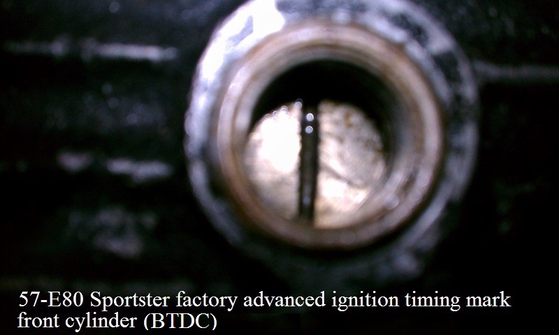
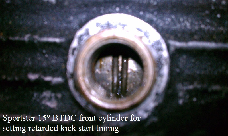
- 57-70 Sportster engines: 40)
- The single straight line is 45° BTDC front cylinder (factory advanced ignition timing setting).
- The double straight lines are 15° BTDC front cylinder (used to set retarded kick start timing).
- The dot is TDC front cylinder (not used for any ignition settings).
The dot is NOT rear cylinder advanced timing like on AMF big twin models.
- 71-E80 Sportster engines:
- The single straight line is 40° BTDC (original factory advanced ignition timing setting).
- The dot is TDC front cylinder.
- The double dots are for rear advanced timing.
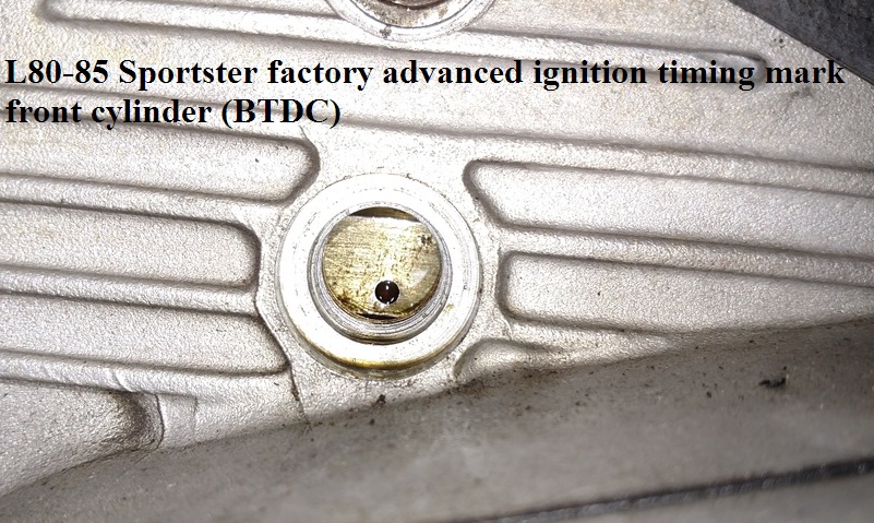
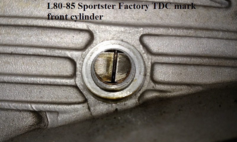
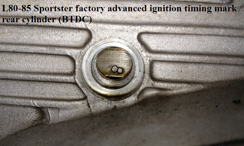
- L80-85 Sportster engines:
The timing marks have been revised on all 1980 and later 1000cc (crankcase number 780-108-001 and up) and 1340cc models.
This was done to enable the timing to be set electronically at the factory.
This step was to reduce the number of timing adjustments required during pre-delivery and set-up.
The procedure used to set the timing is exactly the same. Only the timing marks have changed.
The front cylinder advance timing mark has changed from a straight line to a 1/8” dot and the rear cylinder advanced timing mark now represented by a lazy eight.- The single dot is 40° BTDC front cylinder (factory advanced ignition timing setting).
- The straight line is TDC front cylinder.
- A lazy eight (2 side by side dots) are for rear cylinder advanced timing.


Setting Ignition Timing
- During the 1969 model year, the MoCo began a new practice of setting ignition timing on Electra Glide, Servicar and Sportster models with the circuit breaker cam plate fully advanced instead of in the retarded position done in the past. Correct timing position was changed to 45° BTDC on Sportsters. Good engine performance requires correct advanced timing and this procedure eliminates any variations which may happen , in degrees of timing, due to a tolerance buildup in the timing weight parts. Retarded cam timing is not as critical since it is effective only at low speeds. 47)
- When checking / setting timing with a circuit tester or timing light (according to the FSM), ignition should occur when the single mark on the flywheel is in the center of the timing inspection hole in the crankcase. 48)
- Checking / Setting timing on 1983 → models. 51)
- When checking timing advance, always check the VOES operation See Testing the VOES Operation. Failure to do so may result in running engine with too much spark advance which could lead to extreme engine knock and / or engine failure.
- Ignition timing should be checked every 2500 miles.
- Use an Inductive Timing Light to view the advanced timing of the flywheel through the accessory plastic view plug (HD-96295-65) screwed into the timing inspection hole. Make sure the view plug does not touch the flywheels. Timing light leads should be connected to the front spark plug cable, ground and battery positive terminal. Make sure the vacuum hose is properly installed at the carburetor and at the VOES. Start the engine and set the engine speed at 1300 rpm. Light will flash each time spark occurs. Loosen the sensor plate screws just enough so that plate can be shifted using a screwdriver in the notch as the light (aimed into the inspection hole) stops the timing mark in the center of the hole.
Preparing the timing mark for using a timing light:
Clean the timing mark on the flywheel and apply a paint color that will stand out when viewing it with a timing light. 52)
You can spray some brake cleaner on a Q-tip to clean the timing mark.
Paint the timing mark with bright pink fingernail polish (or something florescent).
Install the clear plug into the timing hole.
It should be very near but not touching the flywheel. (go in until you touch the wheel and back off a 1/8-1/4 turn).
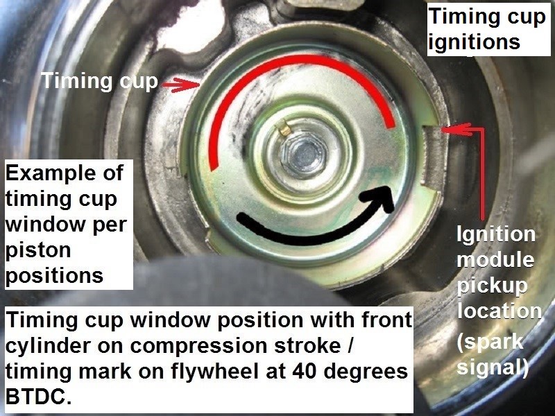
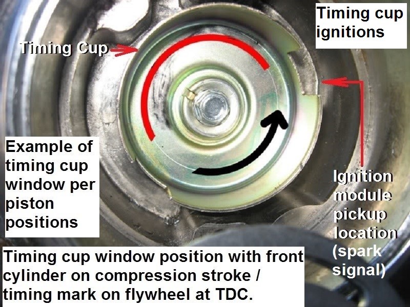
The OEM Timing Rotor used for electronic ignitions on 1980-82 models is 32401-80 (Silver color).
For 1983-later, the OEM Timing Rotor is 32402-83 (Gold color). This later version is usually also used for aftermarket nosecone electronic ignitions installed in Ironhead models.
| Example of timing cup window positions per piston positions. (Crane HI-4 on 73 model) 53) | |
 |  |
Ignition Lubrication
- Only a small amount of Hi-Temp grease is recommended for proper lubrication of the cam surface, camshaft, advance weight pins and underneath the advance weights. Too much grease may melt away during service (Over lubrication can cause grease to migrate between the point contacts causing burning). See your FSM for proper assembly guidelines.
- Ignition advance lubrication change in 1976: Due to normal engine combustion and friction, high temps may be present in the timer compartment and timer components. These high temps could partially dehydrate the installed grease and cause stiffening or gumminess, especially at the pivot pins and timer shaft. Normal operation keeps the assembly free but timer adjustments are more difficult. Since August, on all production engines, the timer weight assemblies and breaker cam posts have been sprayed with “Never-Seez”, a spray can type lubricant when making timer adjustments. Never Seez or Locktite Anit-Sieze was suggested for dealer use along with a high temp grease on the point cam rubbing block. 54)