Table of Contents

IH: Oiling & Lubrication
Oil Pump
Sub Documents
- 57-76 Oil Pump:
- 77-85 Oil Pump:
- Oil Pump Comparisons:
- XR-750 Oil Pump:
Oil Pump Function
The oil pump is a positive displacement unit.
If you block the discharge flow path, discharge pressure will rise and literally approaches infinity until something fails. 1)
It's non-regulated and delivers its entire volume of oil under pressure to the oil filter mount.
However, don't take the term “positive displacement pump” literally. 2)
Compared to a centrifigal pump, gear / gerotor type pumps use displacement to function.
How positive it is depends on what it's pumping.
The most 'positive' pump on our bikes may be the master cyl for the disc brakes.
You pull the lever and it pumps real good, positive, unless there is air in the system.
Then you still get the displacement but not the pressure because liquid is not compressable but air is.
Gear / gerotor type pumps work by filling the spaces between the teeth with whatever it is that is being pumped (oil in our case).
The oil in the tooth spaces gets squezed out of the spaces when the gear teeth mesh together (because a tooth is now in that space.
But there is still a little space left at full mesh.
Gearotor pumps have a smaller space at full mesh than gear pumps.
Now when the mesh breaks, a void is created. Oil gets sucked into that void.
Now what if air is in the spaces instead of oil?
It gets sqeezed out also unless there is pressure (restriction) in the curcuit its trying to flow into.
In that case, some air stays in the spaces and gets compressed in the small space remaining as the teeth mesh.
When the teeth unmesh, air expands (refilling void that should be getting oil sucked into it.
The pump can't make enough pressure to overcome the exit restriction.
Then there is no flow and no ability to reprime itself since.
(it's not making enough suction due to the expansion of the compressed air refilling the void that the oil should be filling)
Eventually the pressure in the return line gets released.
While this is happening oil is building up in the pickup sump and waiting for the return side to come back online.
The supply pump is still pumping while the return is toggling from air locked to primed and pumping.
Think about what state the return oil is in as it collects in the return pickup cavity. It's just been thru a 60 cycle blender.
Our bikes live with that every mile they travel with lots of air whipped into every drop of return oil.
Restrictions in the return side of the pump will lead to a more sustained oil level in the crankcase sump.
(large enough to reduce outflow from the engine to a volume less than the supply pump is feeding the engine)
This is a condition known as wetsumping.
Read more about wetsumping in the REF section of the Sportsterpedia.
Oil Pump RPM (1957-1985)
There are 10 teeth on the drive gear at the pinion shaft and 20 teeth on the oil pump breather gear or driveshaft respectively.
This creates a 2:1 ratio of the gears (20/10 = 2:1) meaning the oil pump RPM is half the speed of the engine.
(running at 4,000 RPM, the oil pump is turning at 2,000 RPM)
Oil Pump Pressure (57-85)
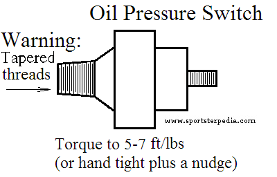
See also Installing an Oil Pressure Gauge in the REF section of the Sportsterpedia.
Engine oil pressure was measured (by the MoCo) with a pressure gauge at the oil pump.
Expected oil pump pressure per FSM's:
Gauge mounted at oil pump:
As checked with hot oil and a gauge at the oil pressure switch location at the oil pump.
The oil pressure switch has to be removed for the gauge to be installed.
1957-1969: 3)
Minimum: 3-7 psi (idle, with spark retarded)
Normal riding conditions: 10-14 psi (6 psi at 20 mph)
1970-1978: 4)
Minimum: 3-7 psi (idle)
Maximum: 15 psi (60 mph in high gear)
Normal riding conditions: 4-15 psi
1979-1985: 5)
Minimum: 4-7 psi (idle)
Maximum: 10-20 psi (3500 rpm)
Normal riding conditions: 4-15 psi
Note: On a cold startup, expect pressure to reach ~60 psi 6)
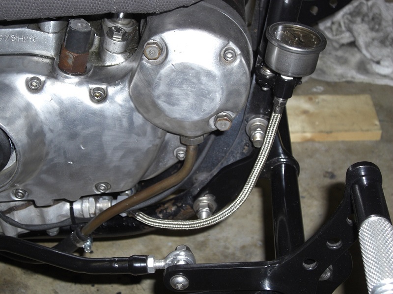
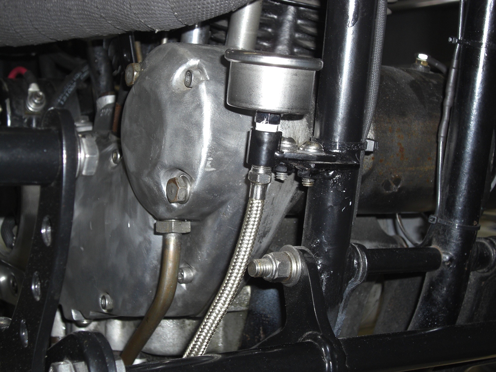
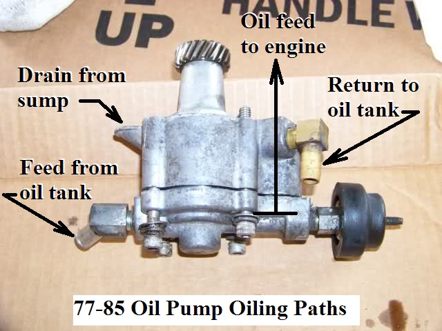
Oil Pump Fittings and Oil Paths
Click Here to reference the Oil Tank, Lines and Routing page in the Sportsterpedia.
- 1977-1985 oil pumps feed oil to the motor from the top side of the pump.
Feed oil goes from oil tank to the lower gerotors and out a hole in the top front of the pump to the cam cover passages.
A drilled hole in the lower front intercepts the feed path to affect the oil sending unit in the front of the pump.
Return oil drops into the “duck bill” on the back of the pump, to the upper gerotors to the top front fitting, to the tank.
Oil Pump Gaskets/Seals
NOTE: Please be sure of your particular parts assembly before ordering seals.
1977-1985 Oil Pumps look pretty much identical before dis-assembly but some parts won't interchange.
Click Here for individual pics of pump assembly parts in the Sportsterpedia.
 |
|||
|---|---|---|---|
| Year Model | Part# | Notes | Pics |
| 1952-1976 K Model, Sportster | 26256-52 | Pump to engine case mounting gasket | Pic 10) |
| L1958-1976 XL, XLH, XLCH | 26227-58 | Gear shaft oil seal | Pic 11) |
| 1952-E1962 K Model, Sportster 1972-1976 XLH, XLCH | 26259-52 | Inner cover gasket | Pic 12) |
| 1952-E1962 K Model, Sportster 1972-1976 XLH, XLCH | 26258-52 | Outer cover gasket | Pic 13) |
| L1962-1971 XLH, XLCH | 26259-62 | Inner cover gasket | Pic 14) |
| L1962-1971 XLH, XLCH | 26258-62 | Outer cover gasket | Pic 15) |
| 1977 (only) Sportster | 12042 | Small o-ring around check valve body (used in 1600 pumps stamped “0”) | Pic 16) |
| 1977-1990 Sportster | 26495-75 | Pump to engine case mounting gasket | Pic 17) |
| 1977-1985 Sportster | 26432-76 26432-76A | Small o-ring around check valve body Updated part# retros to 1977 | Pic 18) |
| 1977-1985 Sportster | 26433-77 | Small o-ring between pump body and cover (over check valve bore) | Pic 19) |
| 1977-1990 Sportster | 26434-76 26434-76A | Big o-ring between pump body and cover (cover seal) Updated part# retros to 1977 | Pic 20) Pic 21) |
| 1977-1982 Sportster | 12036 | Outer divider plate oil seal (between divider plates). Use only with outer plate 26493-75 | Pic 22) |
| 1983-1990 Sportster | 12036A | Shaft oil seal between divider plates. Use only with outer plate 26493-75A | Pic 23) |
Priming the Oil Pump
A dry pump won't pump oil.
Any time you have removed the oil pump or the removed / drained the feed hose from the oil tank, the pump needs to be primed.
- The oil pump needs to be primed with oil / lube before it can transfer oil from the inlet to the outlet cavity inside.
- Prime the oil pump per the FSM;
- Upon removal / inspection, oil the pump internals.
- Remove the oil pressure switch and rotate the engine until oil comes out the end of the pump and reinstall the switch.
- If you let it sit long enough, oil will gravity drain inside the pump and prime it.
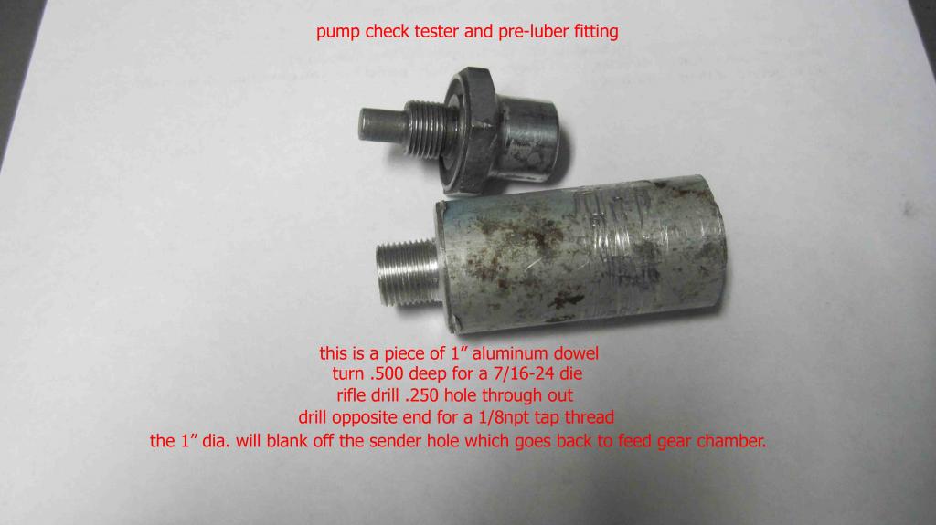
- Another way to prime the pump is to use assembly lube on the gerotors and inside of the pump before installing it. 24)
Then you have an instant hydraulic seal to help the oil pump suck oil from the hose. - You can also using a large syringe with a tapered tip inserted into the oil supply hose on the bottom of the oil tank. 25)
Then you can force feed oil the pump and on to the engine using this technique and it avoids having to mess with the sending unit. - With this homemade tool, all you have to do is use a grease gun (without grease) filled with oil and pump it into the system so a dry start can be avoided.
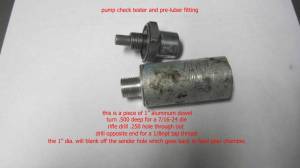 26)
26)
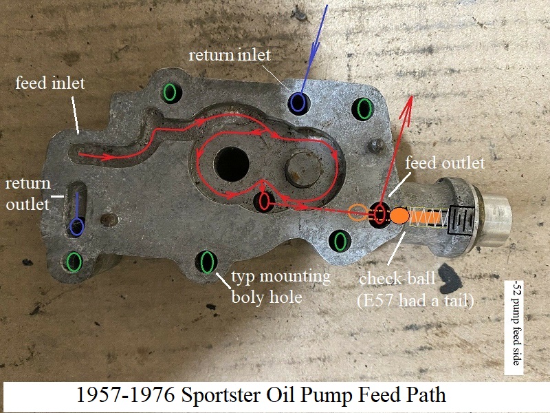
1957-1976 Gear Driven Pumps
Oil Pump Cycle
- The separate oil feed and scavenger (oil return) pumps are gear-type pumps and are incorporated in the same pump housing with a check valve on the oil feed side. The feed section is gravity fed from the oil tank and forced fed from the pump to the engine and back to the scavenger side of the pump which returns oil back to the oil tank. 27)
- In a gear type oil pump, the oil is transferred from the inlet to the outlet side of the pump when it is trapped between the rotating gear teeth and the gear housing.
- The oil pump seldom needs servicing. Therefore, before dis-assembling it for repairs because of no oil pressure, be absolutely certain that all possible related malfunctions have been eliminated. 28)
- If oil in oil tank is diluted, pressure will be affected.
- In freezing weather, the oil feed line may clog up with ice or sludge, preventing circulation.
- Inspect oil pump check valve as it prevents the gravity flow of oil into the crankcase when the engine is not running and provides the correct oil pressure for the operation of the oil signal light switch. If the check valve is not seating properly, oil will bypass the valve and drain oil from the oil tank into the crankcase and upon starting the engine, a considerable amount of oil will be blown out the crankcase breather pipe.
- Check for a grounded oil pressure switch wire or a faulty switch if oil indicator light fails to go out with the engine running.
- If no oil pressure or return oil is not indicated at the oil tank, when engine is running, or an excess amount of oil is blown from the breather pipe, dis-assemble the oil pump for repair. Damage can occur by way of a foreign object lodged in the oil pump gearing. Check your FSM for dis-assembly and repair. 29)
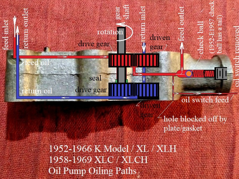
| 1952-1966 K Model / XL / XLH 1958-1969 XLC / XLCH Oil Pump Oiling Routes 30) |
 |
Pump Changes / Features
|
|||
|---|---|---|---|
| Oil Pump Assemblies (per parts catalogs) | |||
| Pump # | Body Casting# | Year Model | |
| 26203-52C | 26215-52 | 1957-1958 | XL, XLH, XLCH |
| 26203-52D | 26215-52 | 1959-E1962 | XL, XLH, XLCH |
| 26203-52E | 26215-52 | L1962-1966 | XL, XLH, XLCH |
| 1967-1971 | XLCH | ||
| 26204-67 | 26215-52 | 1967-1971 | XLH |
| 1970-1971 | XLCH | ||
| 26204-67A | 26215-72 | 1972-1976 | XLH, XLCH |
- There are 3 basic pumps & 2 basic plumbing styles 34)
- Both feed and return are drilled passages in the right crankcase (57-66 all) & (67-69 xlch)
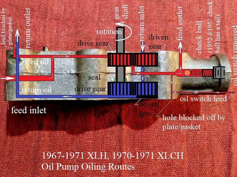
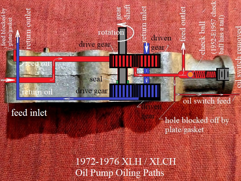
- Only return drilled thru case. feed goes from tank to pump by external hose. (67-69 xlh) & (70-76 all)
- With the correct knowledge any 57-76 pump, or parts of them can be mated to any 57-76 cases. But the combos can get confusing. 35)
- The stock slot in pre & post -72 pump bodies are .345“ 36)
- The stock slot in pre -72 pump gear is .375” 37)
- The stock slot in post -72 pump gear is .625“ 38)
On some pump casting bodies you may see an Allen plug in the back of the pump. 39)
Also the earlier pumps had a casting number of -52.
In 1972 and with the birth of the 1000cc engine, the pump numbers were -72.
It had larger gears and a bigger breather slot.
1957-E1962
- There are (3 variations) and these all use 16t gear sets and style 1 plumbing 42)
- The production changes made during its run: 43)
- 1957-E1958: Baseline pump that all others came from.
It has no oil seal and uses a snap ring and a full profile woodruff key at the scavenge gear. - L1958-1959: The body is now machined for an oil seal.
- 1960-E1962: The retaining ring at the scavenge gear was replaced by half moon retainers.
The scavenge drive gear is counter-bored for these half moons and the woodruff key is shortened so it won't interfere with the half moons.
L1962-1971
- There are (2 variations) and all these used 14t gears & scavenge sets got taller than the previous 16's were. 50)
- All use half moon retainers and the shortened woodruff key on the scavenge drive.
- All bodies made up to 1966 are for internal feed and scavenge plumbing (plumbing style 1).
- In 1967, the rear of the body gets tapped for the external feed fitting for use on 1967-1969 XLH. This is when style 2 plumbing started.
- Bodies tapped for style 2 were still used with the addition of a plug in the new rear hole on 1967-1969 XLCH (style 1 cases).
1972-1976
- These have (no variations) and go back to 16t gears and a snap ring with long key 55)
- Feed gears are the same as 1957-E1962 but the scavenge set is now wider again (wider than any of the previous sets).
- Breather gear gets enlarged slots in it. 56)
- Body and breather housing get an extra hole (2 holes now) drilled in them for additional return capacity, cases also get extra matching hole. 57)
- Solid feed gear drive pin gets replaced by the hated roll pin. 58)
- Dowels between body and breather housing are now history. 59)
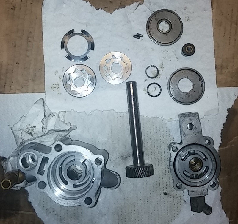
- Each complete pump breaks down into these components: 60)
- Breather or sleeve gear-has the 2 slots in it
- Breather gear housing- cast iron part that breather rides in
- Feed gear set and drive pin (the skinnier of the 2 gear sets)
- Pump body
- Scavenge gear set and drive key and retaining clip.
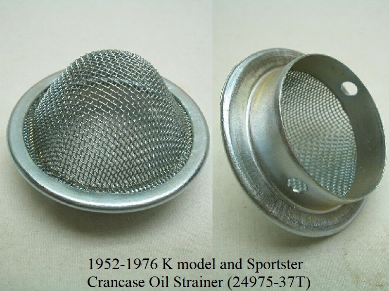
Return Oil Screen (in gearcase)
1952-1976 K models and Sportsters have an oil return strainer in the bottom of the gearcase.
The strainer is part# (24975-37) and it is fixed in place by a dowel (333) staked into the side of the case.
Oil collects in the gearcase, flows through the screen and down a passage to the oil pump return gears.
Sportsters have a gasket (24978-57) under the strainer.
Strainer (24975-37T) superseded the original strainer part#.
XR/XLR Oil Pumps (only)
- From 1970 to 1989, the gear driven oil pump went through several changes.
- 1980-up XR750 got a smaller hole thru the crankpin for oiling per the FSM.
- 1952-1968 KR, KRTT, XLRTT
1970 XR750 Oil Pump (26203-54RA): 71):- Feed pump speed was 1/4 of the engine speed.
- A 15 psi bypass spring in the pump determines the pressure.
- KR oil pump pressure taken at oil pressure switch should be 12-15 psi (at 5000 RPM-higher with hot oil).
- XLR oil pump is factory pre-set to 5 psi.
- This pump can be used instead of the 1/2 speed pump on XLs but will have lower oil pressure. Only use for maximum performance (race only).
- 1972 XR-750 Oil Pump (26203-54RB):
- Feed pump speed was 1/4 of the engine speed and the return side operated at a 2:1 ratio of the feed side.
- The breathing system was used to return oil from the crankcase into the cam / gear cover.
- From there the oil drained directly onto the return gears of the oil pump. 72)
- 1975-1987 Oil Pump (26203-74R):
- The engine had a separate oil sump bolted to the crankcase.
- Feed pump speed was 1/4 of the engine speed and the return side operated at a 2:1 ratio of the feed side.
- Return gears scavenged the crankcase oil through an external oil line. 73)
- 1988-2003 XR-750 Oil Pump (26203-88R):
- The same design of the '75' pump.
- Had more efficient drive gear design and improved oil routing.
- Feed pump speed was doubled to 1/2 of the engine speed and the return side operated at a 4:1 ratio of the feed side.
- The oil pump drive gear was re-activated as a breather only. 74)
1977-1985 Gerotor Driven Pumps
Oil Pump Cycle
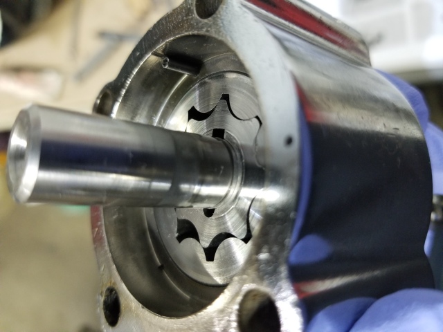
- The oil pump is fitted with gerotors instead of gears consisting of two gerotor pumps in the same pump housing.
The pump is gravity fed from the oil tank. The feed pump forces oil to the engine while the scavenger pump collects and returns oil back to the oil tank. - A gerotor type pump has 2 elements, an inner (which always has one less tooth than the outer) and an outer gerotor.
Both elements are mounted on fixed centers but are eccentric to each other. 75)
- In a gerotor type pump, oil is transferred from the inlet to the outlet as it is trapped between the rotating inner and outer gerotors. 76)
- All Sportster gerotor pumps (77 and up) turn clockwise when viewed from the top.
(as opposed to 76 and older pumps that turn counter clockwise) 77)
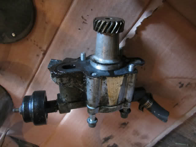
- The gearshaft is in a worm gear configuration with the drive gear on the pinion shaft.
- During the first 180 degrees of rotation, the cavity between the inner and outer elements gradually increases in size.
Maximum cavity volume is equal to the full volume of the missing tooth.
The gradually enlarging cavity creates a vacuum into which the oil flows out from the inlet. - During the next 180 degrees of rotation, the size of the cavity decreases forcing oil into the outlet.78)
- Oil is forced into a valve with a one way spring loaded cup set at 1-1/2 psi.
From that valve, oil exits the pump and enters the crankcase. Oil pressure is indicated by the oil pressure switch. 79)
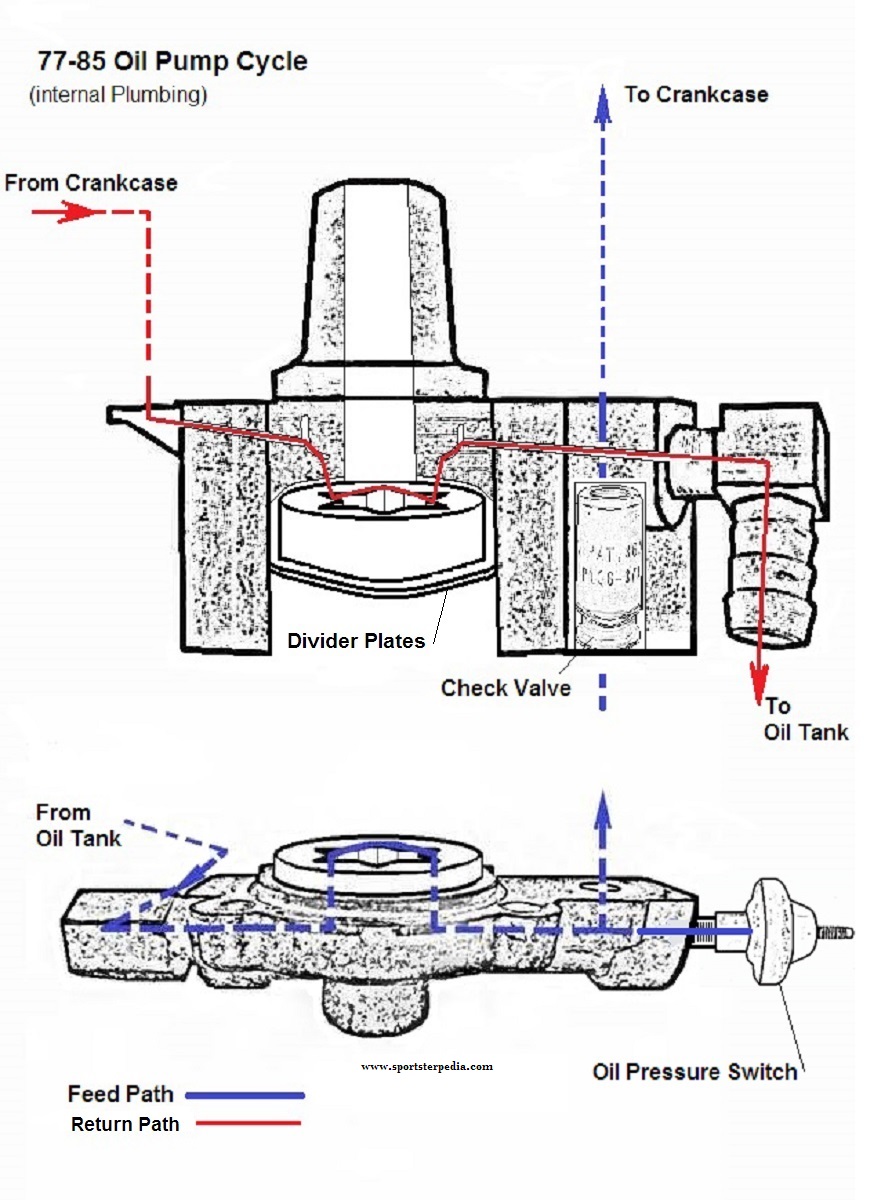
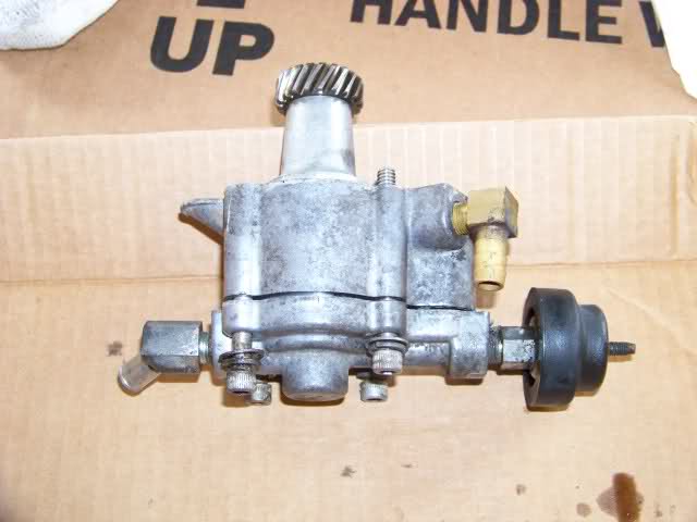
- This pump has two hose fittings; 82)
- The rear fitting is the oil feed.
- The front fitting (above the oil pressure switch) is the oil return.
- Simplified cycle;
- The oil will go from the bottom of the oil tank to the rear fitting on the oil pump.
- Then, the oil will return from the front fitting of the oil pump to the oil tank.
Pump Changes / Features
See the link in the sub documents above for 77-85 Oil Pump - Parts Lists and Upgrades.
- There are 2 basic pumps:
- 77-E83 (4 versions)
- L83-85
- Only 1 plumbing style:
- The oil pump gets gravity fed oil from the tank by an external hose.
- Oil feed to the engine is a drilled passage in the right crankcase fed internally straight from the oil pump.
- Return oil is sent through a fitting at the pump to the oil tank by an external hose.
- Any 77-85 oil pump can be mated to 77-85 cases as a unit. Mixing internal parts gets a little tricky.
- 77-E83 gerotors can be used in L83 and up pumps.
- L83 gerotors can only be used in L83 style pumps.
- There were 2 different outer separator plates used from 77-85 with different IDs.
- Each has it's own type gearshaft seal that must be used with it.
- Each plate will fit any 77-85 oil pump as a set with it's specific seal.
- See “77-85 Oil Pump Parts Lists and Upgrades” above for the complete list and years for all the changes.
 |  |  |
| 79 Oil Pump 87) | ||
Oil Pump Drive Gears (1957-1985)
Gear Configuration
The gear mesh (oil pump driveshaft gear to drive gear on the pinion shaft) looks to be a worm gear configuration.
However, that is not accurate. It's actually two right handed helical gears in a 90 degree configuration (or cross axis helical gears).
The teeth on these gears stay in contact longer than straight teeth spur gears. 88)
(which allows them to transmit higher loads at higher speeds than spur gears)
The gears are carbon steel for strength with hardened teeth for increased wear resistance.
(once axial play wears the hardness, the teeth wear down rather quickly)
For the gears to mesh correctly, they must have the same pressure angle and pitch.
Helical gears can be configured to transmit motion in a straight line (or used for Sporty oil pumps at a 90° angle).
To transmit motion at a 90° angle, 2 gears are paired in the same tooth direction (right handed).
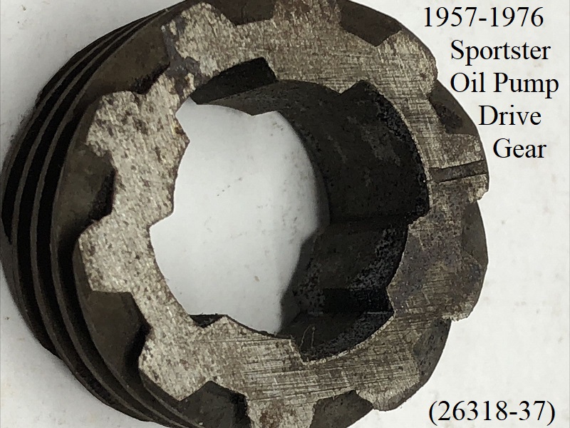
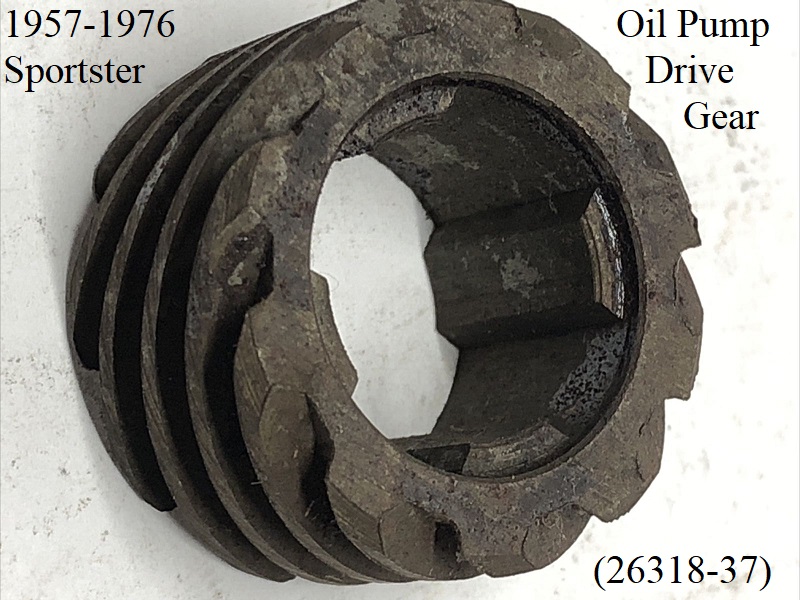
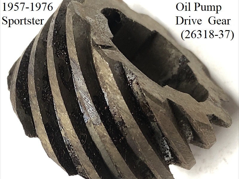
57-76 Oil Pump Drive Gear
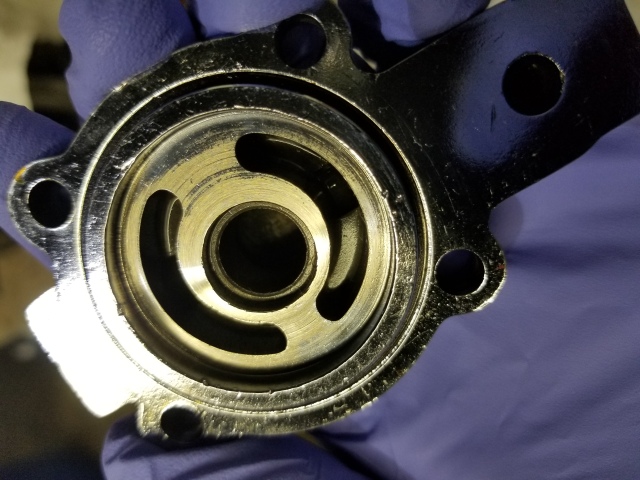
The 57-76 pinion shaft has 4 external splines and one is longer than the other three.
The 57-76 oil pump drive gear (26318-37) has 4 internal splines that match to the pinion shaft with one longer recess between them and is a slip fit over the shaft.
The drive gear slides onto the pinion shaft one way (only) with a timing mark in the front over the wider recess.
You can't install the drive gear in any 360° position where it will fit on the shaft and it's timing mark does not line up with the pinion gear timing mark.
The timing mark on the front of the drive gear isn't used to time anything but may simply be there to distinguish that to be the front of the gear.
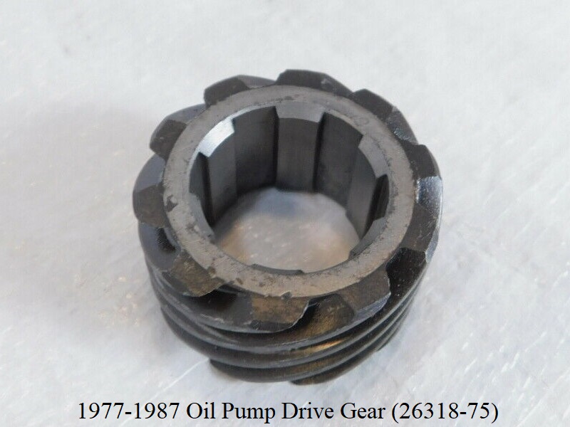
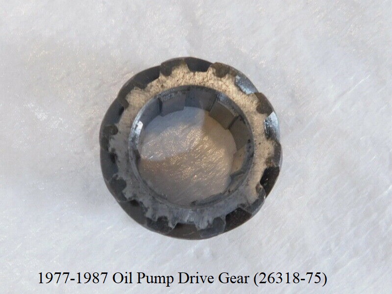
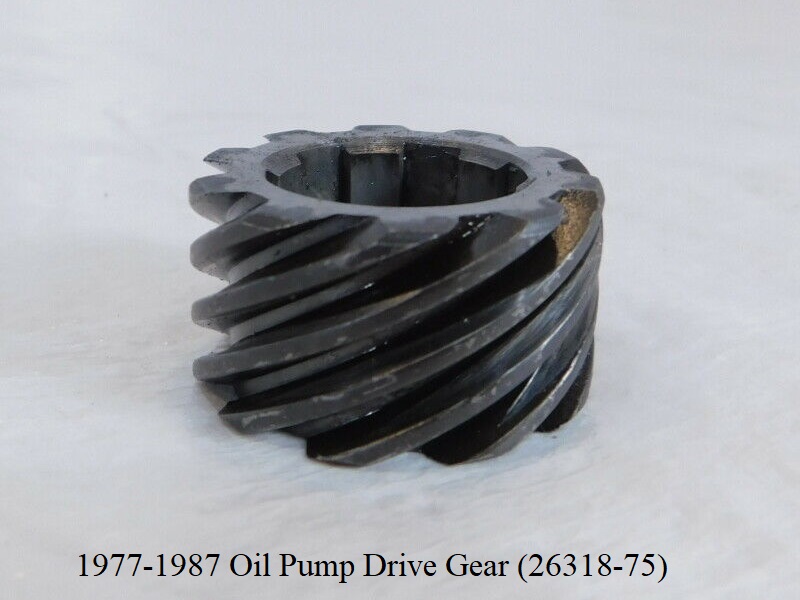
1977-1987 Oil Pump Drive Gear
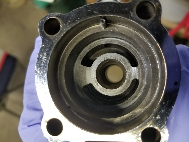
The 1977-1987 pinion shaft has 6 external splines all being the same length.
The 1977-1987 oil pump drive gear (26318-75) has 6 internal splines that match to the pinion shaft and is a slip fit over the shaft.
The drive gear slides onto the pinion shaft with no direct radial or front to back positioning and has no timing mark.
So you can install the drive gear in any position where it will fit on the shaft (has no front or back either).
| 1977-1987 Sportster Oil Pump Drive Gear 92) | ||
 |  |  |
3)
1959-1969 HD FSM pgs 3A-11, 3A-15
4)
HD 70-78 FSM pgs 3-1, 3-5
5)
1979-1985 HD FSM pgs 3-1, 3-10
9)
photo by ironheadjunkie of the XLFORUM, labeled by Hippysmack
18)
photo courtesy of Ebay seller, Rusty Dusty Motorcycle Parts. Link to Ebay Store
19)
photo courtesy of Ebay seller, animalhouse2010, Link to Ebay store:
20)
photo courtesy of C & M Sales, Link to Ebay Store
21)
photo courtesy of Ebay seller, Robison Motorcycles, Link to Ebay Store
22)
photos courtesy of Ebay seller, 57harleyrider. Link to Ebay Store
23)
photos courtesy of Boneyard Cycles in Melbourne, FL
33)
photo by rockeyschopshop, labeled by Hippysmack
57)
Dr Dick of the XLFORUM https://www.xlforum.net/showpost.php?p=3272806&postcount=204
70)
Gear ratios provided by the 1972-2003 XR750 manual
71)
KR, KRRTT and XLRTT Manual
77)
needspeed of the XLFORUM https://www.xlforum.net/showthread.php?t=2071153&page=7
81)
photo by Hippysmack
92)
photos courtesy of c3cycle.com, Link to site: https://www.c3cycle.com/