This is an old revision of the document!

REF: Service Procedures 11B
Setting 1991-2003 Shift Pawl Position
The FSM says to lift the shifter pawl over the pins, loosely install the washer and nuts for the assembly, install the detent plate and place the transmission in 3rd gear.
Then use a #32 (.116“) drill bit into the hole in the detent plate between the pawl and top pin, push down on the top (crank) of the assembly and tighten the nuts.
This leaves a smaller gap between the bottom of the pawl and second pin.
However, collective minds believe the pawl should be adjusted so the hook on each end should be equal distance to the top and bottom pins respectively.
Inaccurate way of checking the distance between the pawl and pins:
In the first pic below, the pawl was pulled up snug against the bottom pin and putty was pushed into the gap at the top.
With the putty removed and measured, the gap between the top pawl hook and pin was .180”
To center the pawl between the pins would take a .090“ drill bit or pin for the equal distance top and bottom.
The second pic shows the distance top and bottom left after installing the .116” drill bit (custom .116“ tool shown below).
So, to center the pawl, it would take a .090” drill bit / pin into the detent plate to set the pawl equal top to bottom.
This is not correct!
More accurate ways of measuring the total gap:
The way the distance is measured will have huge variations unless it is done with the detent plate in place first.
After the shifter shaft back plate is tighten down, the shaft, arm and pawl assembly will still have 4-way movement (L-R-Up-Down).
The only way to get the pawl set close to it's operating position is to install the detent plate.
To measure the total distance, as was done below, you'll need to brace the shaft while the detent plate is installed and pushed against the pawl.
Then remove the detent plate without disturbing the shaft (held with one hand) while turning the shaft with the other hand against the bottom pin.
Then the gap between the pawl and top pin can be measured.
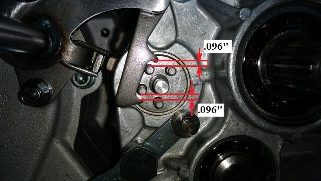
XLF member LenC found that it took a .096“ drill bit to center his pawl between the pins (total gap of .192”).
The total gap was measured with gauge pins.
Another measurement taken from Hippysmack with a hole gauge equals to a .101“ bit to center the pins (total gap of .202”)
The differences in the two measurements may be the way they were measured or it may be normal wear or manufacturing tolerances that are different.
The shift pawl length between the pin hooks was measured below as was the outside to outside of the mating pins.
With the pawl at .840“ and the pins at .640”, there would be exactly .200“ of gap between the top pin and the hook if the the bottom hook was snugged against the pawl.
However, when the shifter shaft is turned one way or the other, the pawl doesn't hook the pins directly centered between the hooks on the pawl.
See the pic below, the pawl pushes down on the top pin while snugged against it and there is a space between the pawl and the lower pin.
Likewise when the pawl picks up on the lower pin, there is a space between the pawl and upper pin.
The body of the shift pawl between the hooks is tapered from the installed view top to bottom. And the hooks are offset from the body of the pawl.
Using the factory .116” Spec:
The FSM says to use a #32 drill bit (.116“) between the pawl and the top pin.
If you set that accordingly, pull off the detent plate and look at the remaining gap just created between the pawl and top pin, it looks like the top is way high.
However, if you hold up the shaft straight out as if it were in the primary cover hole, the distance looks much more centered.
From the dims above, the pawl ID between the hooks is .840” and the OD from two adjacent pins is .640“.
This leaves .200” total gap between the pawl and the pins divided by 2 is .100“ gap between pawl and pin (top and bottom).
When you set the spec to .116”, you are setting a vertical distance but the inline direction between the pins is at an angle.
So in theory, if you set that distance to a vertical .100“, the top would then be lower (less gap distance) than the bottom.
The extra .016” for the drill bit should account for the angle the bit is at when setting the distance.
This should equate to .100“ setting the pawl equal inline distance to the top and bottom pins.
Example:
![]()
![]()